Supercharge Your Innovation With Domain-Expert AI Agents!

Central hole forming device for blank drilling for industrial part machining

A technology of parts processing and blank parts, which is applied in the field of drilling devices, can solve problems such as time-consuming and laborious, and achieve the effects of convenient operation, stable steel rods, and accurate drilling positions

Active Publication Date: 2021-07-13
QINGDAO SANLIAN METAL STRUCTURE
View PDF5 Cites 2 Cited by
  • Summary
  • Abstract
  • Description
  • Claims
  • Application Information

AI Technical Summary

Problems solved by technology

[0004] In order to overcome the possible deviation of the position of the hole, which reduces the work efficiency of people, if the number of steel rods that need to be holed is large, it will also lead to the shortcomings of time-consuming and labor-intensive people. The technical problem of the present invention is to provide an automatic opening A central hole opening device for drilling blanks for industrial parts processing with accurate hole and hole opening positions and easy operation

Method used


Image

  • Central hole forming device for blank drilling for industrial part machining
  • Central hole forming device for blank drilling for industrial part machining
  • Central hole forming device for blank drilling for industrial part machining

Examples


Embodiment 1

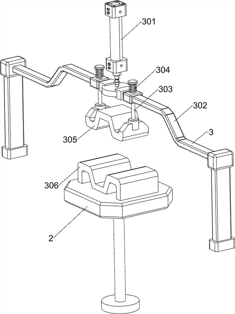
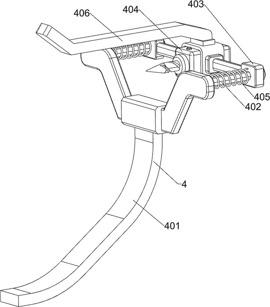
[0029] A central hole opening device for drilling blanks for industrial parts processing, such as figure 1 , figure 2 , image 3 and Figure 4 As shown, it includes a base 1, a support frame 2, a pressing assembly 3 and an opening assembly 4. The upper middle part of the base 1 is rotatably provided with a supporting frame 2, and the upper middle part of the base 1 is provided with a pressing assembly 3. The upper right side of the base 1 A hole assembly 4 is provided on the side.

[0030] The compression assembly 3 includes a cylinder 301, a first movable frame 302, a first slide bar 303, a first spring 304, a first pressing plate 305 and a shelf 306, the middle side of the top of the base 1 is provided with a cylinder 301, and the telescopic rod of the cylinder 301 The first movable frame 302 is provided on the top, and the first movable frame 302 is slidingly matched with the base 1. The front and rear sides of the first movable frame 302 are slidably provided with a fi...

Embodiment 2

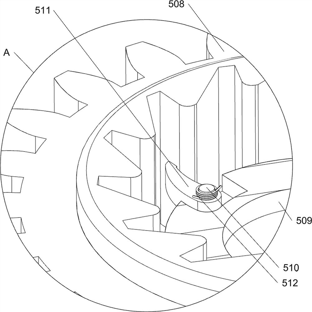
[0034] On the basis of Example 1, such as Figure 5 , Figure 6 , Figure 7 , Figure 8 and Figure 9 As shown, a rotating assembly 5 is also included, and the rotating assembly 5 includes a second bracket 501, a second guide rod 502, a third spring 503, a third movable frame 504, a first pressing rod 505, a rack 506, a bearing 507, The first toothed turntable 508, the first turntable 509, the pole 510, the pawl 511 and the torsion spring 512, the front side of the base 1 is symmetrically provided with two second brackets 501, and the top of the second bracket 501 on the same side is provided with There are second guide rods 502, and a third movable frame 504 is arranged in a symmetrical sliding manner between the second guide rods 502. Two third springs 503 are connected between the outside of the third movable frame 504 and the second bracket 501. The springs 503 are respectively sleeved on the second guide rod 502, and the lower part of the front side of the second mova...


PUM


Abstract

The invention relates to a hole forming device, in particular to a center hole forming device for blank drilling for industrial part machining. The technical problem of the invention is to provide the center hole forming device for blank drilling for industrial part machining, which is automatic in hole forming, accurate in hole forming position, and convenient to operate. According to the embodiment, the center hole opening device for blank drilling for industrial part machining comprises a base, a supporting frame, a pressing assembly and a forming assembly; the supporting frame is rotationally arranged in the middle of the upper portion of the base; the pressing assembly is arranged in the middle of the upper side of the base; and the forming assembly is arranged on one side of the base. The device has the beneficial effects that people place a steel rod on a storage rack, and then start an air cylinder and a centering hole forming drill bit, a second contact rod can drive a first contact rod to move towards the left side, the first contact rod can drive a second movable rack and the centering hole forming drill bit to move towards the left side, and when the centering hole forming drill bit makes contact with the steel rod, the steel rod can be drilled.

Description

technical field [0001] The invention relates to a hole-drilling device, in particular to a central hole-drilling device for drilling blanks for industrial parts processing. Background technique [0002] Due to the needs of the construction industry, it is often necessary to drill holes on both sides of the steel pipe. However, most of the existing drilling machines use manual flipping to drill holes on different sides of the steel pipe, and then hold the drill bit to drill holes. This operation has a large Man-made, the location of the hole may be shifted, which reduces the work efficiency of people. If the number of steel rods that need to be drilled is large, it will also lead to time-consuming and labor-intensive situations for people. The heat and sparks generated during the hole may cause cause people to be injured. [0003] Therefore, it is particularly necessary to design a central opening device for drilling blanks for industrial parts processing with automatic open...

Claims


Application Information

Patent Timeline
IPC IPC(8): B23B41/00B23B47/22B23Q3/00B23Q7/00B23Q11/10
CPCB23B41/00B23Q3/00B23Q7/00B23Q5/34B23Q11/10B23Q2703/04
Inventor 陈文辉
Owner QINGDAO SANLIAN METAL STRUCTURE
Features
  • R&D
  • Intellectual Property
  • Life Sciences
  • Materials
  • Tech Scout
  • Unparalleled Data Quality
  • Higher Quality Content
  • 60% Fewer Hallucinations
Learn More