Improved numerical control lathe

A numerical control lathe and an improved technology, applied in the field of numerical control lathes, can solve the problems such as the inability to clean and collect iron scraps, and achieve the effects of improving self-cleaning efficiency, increasing efficiency, and improving resilience.

Inactive Publication Date: 2021-07-13
商志全
View PDF7 Cites 2 Cited by
  • Summary
  • Abstract
  • Description
  • Claims
  • Application Information

AI Technical Summary

Problems solved by technology

[0006] Aiming at the deficiencies of the prior art, the present invention provides an improved numerical control lathe, which solves the problem that the device cannot realize the cleaning and collection of iron scraps during mold processing, improves the self-cleaning efficiency of the lathe, and improves the recovery of iron blocks. The elastic force greatly increases the efficiency of iron ejection, improves the practicability of the device, and achieves the purpose of using the sound of metal impact to remind the staff to recycle the iron filings, preventing excessive accumulation of iron filings and affecting the device. collection function, improve collection efficiency

Method used


Image

  • Improved numerical control lathe
  • Improved numerical control lathe
  • Improved numerical control lathe

Examples


Embodiment 1

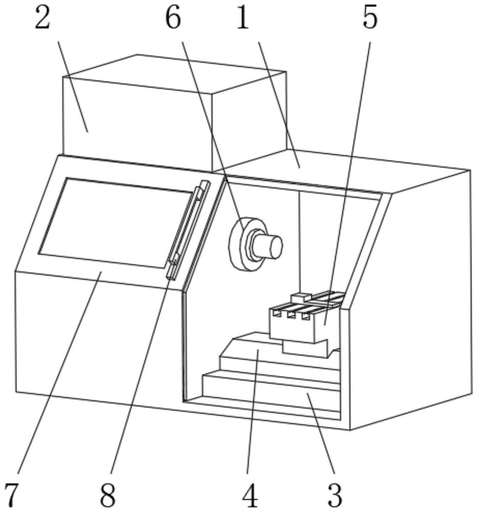
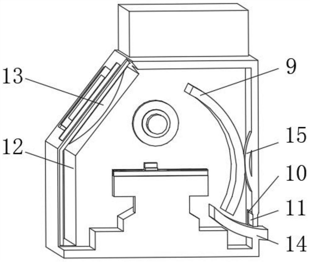
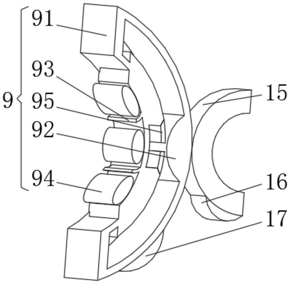
[0029] see Figure 1-3 , the present invention provides a technical solution: an improved numerical control lathe, comprising a housing 1, the top of the housing 1 is fixedly connected with a control frame 2, the inner bottom of the housing 1 is fixedly connected with a base 3, and the base 3 is away from the side of the housing 1 Fixedly connected with a fixed slider 4, the side of the fixed slider 4 away from the base 3 is slidably connected with a knife holder 5, the inner wall of the casing 1 is equipped with a clamp 6, and one side of the casing 1 is slidably connected with a sliding door 7, and the sliding door 7 One side is fixedly connected with a door handle 8, the inner wall of the shell 1 is equipped with a magnetic device 9, the side of the shell 1 near the magnetic device 9 is provided with a material intake 10, and one side of the material intake 10 is rotatably connected with a baffle plate 11.

[0030] The magnetic device 9 includes an arc-shaped frame 91, an e...

Embodiment 2

[0034] see Figure 1-4, the present invention provides a technical solution: on the basis of Embodiment 1, a rectangular slot 12 is provided on the side of the housing 1 close to the sliding door 7, and an ejection device 13 is installed on the side of the sliding door 7 close to the rectangular slot 12, and the ejection device 13 includes an ejection frame 131, one side of the ejection frame 131 is fixedly connected with the sliding door 7, the inside of the ejection frame 131 is fixedly connected with a rotating shaft 132, and the outer side of the rotating shaft 132 is provided with a rotating plate 133, and one side of the rotating plate 133 is fixed Connected with a spring 134, the end of the spring 134 away from the rotating plate 133 is fixedly connected with the ejection frame 131, the top of the ejection frame 131 is fixedly connected with an elastic pull cord 135, and one end of the elastic pull cord 135 is fixedly connected with a slider 136, the slider 136 One side...

Embodiment 3

[0039] see Figure 1-5 , the present invention provides a technical solution: on the basis of Embodiment 2, a collection device 14 is installed in the inside of the housing 1 close to the feeding port 10, the collection device 14 includes a collection frame 141, and the interior of the collection frame 141 is fixedly connected with Squeeze the air bag 142, the inner wall of the collection frame 141 is slidably connected with a semicircle block 143, one side of the semicircle block 143 is symmetrically equipped with an elastic rod 144, and the end of the elastic rod 144 away from the semicircle block 143 is fixedly connected with a metal ball 145.

[0040] When in use, the iron filings collected intensively fall onto the collection frame 141, and the gravity of the iron filings accumulated on the collection frame 141 increases continuously. The expansion volume increases, and the semicircular block 143 is pushed outward. At this time, the semicircular block 143 shakes to drive ...


PUM


Abstract

The invention discloses an improved numerical control lathe. The improved numerical control lathe comprises a shell, and is characterized in that the top of the shell is fixedly connected with a control frame; the bottom of the inner side of the shell is fixedly connected with a base; the side, far from the shell, of the base is fixedly connected with a fixed slide block; the side, far from the base, of the fixed slide block is slidingly connected with a tool apron; a fixture is mounted on the inner wall of the shell; one side of the shell is slidingly connected with a slide door; one side of the slide door is fixedly connected with a door handle; a magnetic device is mounted on the inner wall of the shell; a taking port is formed in the side, near the magnetic device, of the shell; one side of the taking port is rotationally connected with a baffle plate; a rectangular groove is formed in the side, near the slide door, of the shell; and an ejection device is mounted on the side, near the rectangular groove, of the slide door. The invention relates to the technical field of numerical control lathes. By the improved numerical control lathe, the purpose of cleaning and collecting iron chips in mold machining is realized, and the self-cleaning efficiency of the lathe is improved.

Description

technical field [0001] The invention relates to the technical field of numerical control lathes, in particular to an improved numerical control lathe. Background technique [0002] CNC lathe is one of the most widely used CNC machine tools at present. It is mainly used for cutting the inner and outer cylindrical surfaces of shaft parts or disk parts, the inner and outer conical surfaces of arbitrary cone angles, the complex rotary inner and outer curved surfaces, cylinders, and conical threads, etc., and can perform grooving, drilling, reaming, and reaming. Holes and borings etc. [0003] For example, Chinese patent CN108555670B proposes a numerically controlled lathe, including a machine tool, and a chip removal module; The chip module is used to receive the cutting chips produced by the machine tool. The chip removal module is equipped with an inclined sieve plate. When the box swings back and forth, the balls are used to make the bar swing in a snake shape. On the one ...

Claims


Application Information

Patent Timeline
Patent Type & Authority Applications(China)
IPC IPC(8): B23Q11/00
CPCB23Q11/0064B23Q11/0089
Inventor 商志全
Owner 商志全
Why Eureka
Try Eureka