Self-cleaning concrete stirring device

A technology of mixing device and concrete, which is applied to cement mixing device, clay preparation device, mixer accessories, etc., can solve the problem of inability to clean the mixing rod, and achieve the effect of improving efficiency, improving cleaning efficiency and improving practicability.

Active Publication Date: 2021-10-12
启东市建筑机械厂有限公司
View PDF8 Cites 2 Cited by
  • Summary
  • Abstract
  • Description
  • Claims
  • Application Information

AI Technical Summary

Problems solved by technology

[0006] Aiming at the deficiencies of the prior art, the present invention provides a self-cleaning concrete mixing device, which solves the problem that the device cannot clean the mixing rod when processing concrete mixing, facilitates the falling of the concrete on the stirring rod, and improves The efficiency of self-cleaning is improved, the efficiency of cleaning the soil adhered to the mixing rod is greatly improved, the practicability of the device is improved, the concrete on the inner wall is scraped, and the cleaning efficiency of the inner wall of the mixing tank is improved, avoiding The accumulation of concrete in the mixing tank affects the mixing efficiency

Method used


Image

  • Self-cleaning concrete stirring device
  • Self-cleaning concrete stirring device
  • Self-cleaning concrete stirring device

Examples


Embodiment 1

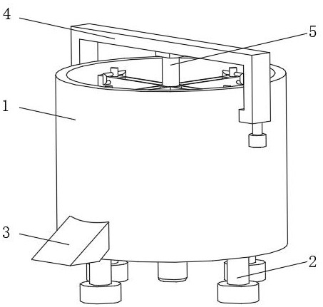
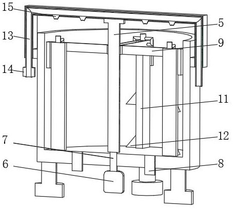
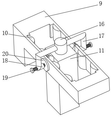
[0030] see Figure 1-4 , the present invention provides a technical solution: a self-cleaning concrete mixing device, including a mixing bucket 1, a support base 2 is evenly installed on the bottom of the mixing bucket 1, a discharge bin 3 is connected to the outside of the mixing bucket 1, and the bottom of the mixing bucket 1 The position away from the discharge bin 3 on the outside is fixedly connected with a fixed frame 4, the bottom of the fixed frame 4 is rotatably connected with a rotating roller 5 through a rotating seat, the bottom of the mixing bucket 1 is fixedly connected with a drive motor 6, and the output end of the drive motor 6 is rotatably connected There is a rotating rod 7, and one end of the rotating rod 7 runs through the mixing tank 1 and is fixedly connected with the rotating roller 5. The bottom of the mixing tank 1 is symmetrically connected with a water outlet pipe 8, and the outer side of the rotating roller 5 is evenly set with a limit frame 9, a li...

Embodiment 2

[0038] see Figure 1-5 , the present invention provides a technical solution: on the basis of Embodiment 1, a rectangular groove 22 is provided on one side of the stirring rod 11, the inner wall of the rectangular groove 22 is evenly installed with a limit shaft 23, and the outer side of the limit shaft 23 is sleeved with Rotating plate 24, rotating plate 24 is rotationally connected with limit shaft 23, one side of rotating plate 24 is provided with sawtooth groove 25 symmetrically, one side of rotating plate 24 is fixedly connected with return spring 26, and returning spring 26 is away from one end of rotating plate 24 It is fixedly connected with the rectangular groove 22.

[0039] Stirring bar 11 is equipped with folding plate 27 near the side of rectangular groove 22, and the top of folding plate 27 is evenly equipped with brush head 28, and the top of brush head 28 is evenly equipped with bristle.

[0040] During use, the driving motor 6 drives the stirring rod 11 to ro...


PUM


Abstract

The invention discloses a self-cleaning concrete stirring device. The self-cleaning concrete stirring device comprises a stirring barrel, wherein supporting bases are uniformly mounted at the bottom of the stirring barrel; the outer side of the stirring barrel communicates with a discharging bin; the position, away from the discharging bin, of the outer side of the stirring barrel is fixedly connected with a fixed frame; the bottom of the fixed frame is rotatably connected with a rotary roller through a rotary base; the bottom of the stirring barrel is fixedly connected with a drive motor; the output end of the drive motor is rotatably connected with a rotary rod; one end of the rotary rod penetrates through the stirring barrel and is fixedly connected with the rotary roller; the bottom of the stirring barrel symmetrically communicates with water outlet tubes; the outer side of the rotary roller is uniformly sleeved with limiting frames; and cleaning devices are uniformly mounted at the inner sides of the limiting frames. The invention relates to the technical field of building machinery. The self-cleaning concrete stirring device realizes the cleaning purpose on a stirring rod, is convenient for concrete on the stirring rod to drop, and improves self-cleaning efficiency.

Description

technical field [0001] The invention relates to the technical field of construction machinery, in particular to a self-cleaning concrete mixing device. Background technique [0002] Concrete mixing is an operation method that mixes cement, lime, water and other materials and mixes them evenly. Concrete mixing is divided into two types: manual mixing and mechanical mixing of water. Concrete mixing stations are widely used in my country's industry, agriculture, transportation, national defense, In water conservancy, municipal and other construction projects, the demand is constantly increasing. Although domestic concrete mixing equipment is constantly innovating and progressing on the basis of borrowing foreign products, the technical level is gradually improving. [0003] For example, Chinese patent CN111168850A proposes a concrete mixing device with cleaning function, which includes a main body, four brackets are arranged at the lower end of the main body, a first sliding cha...

Claims


Application Information

Patent Timeline
Patent Type & Authority Applications(China)
IPC IPC(8): B28C5/16B28C5/08B08B9/087B01F15/00
CPCB28C5/16B28C5/0806B28C5/0862B08B9/087
Inventor 方晨诚
Owner 启东市建筑机械厂有限公司
Why Eureka
Try Eureka