Wing assembly
A wing and component technology, applied in the field of aircraft wings, can solve problems such as poor cruise performance
- Summary
- Abstract
- Description
- Claims
- Application Information
AI Technical Summary
Problems solved by technology
Method used
Image
Examples
Embodiment 1
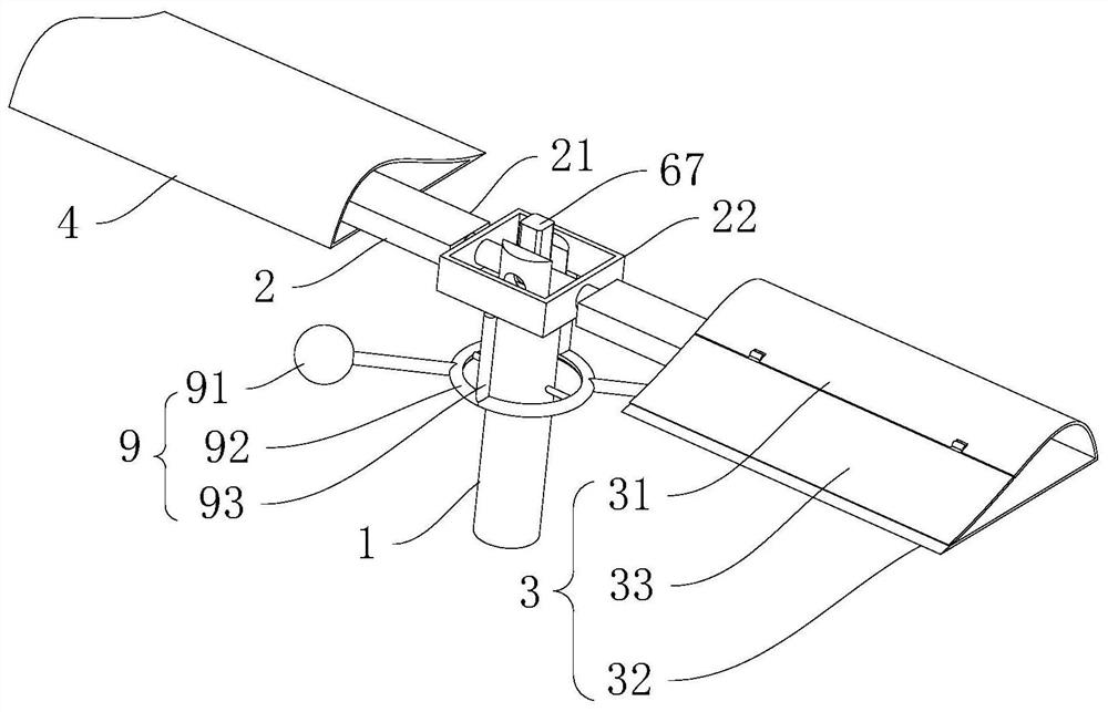
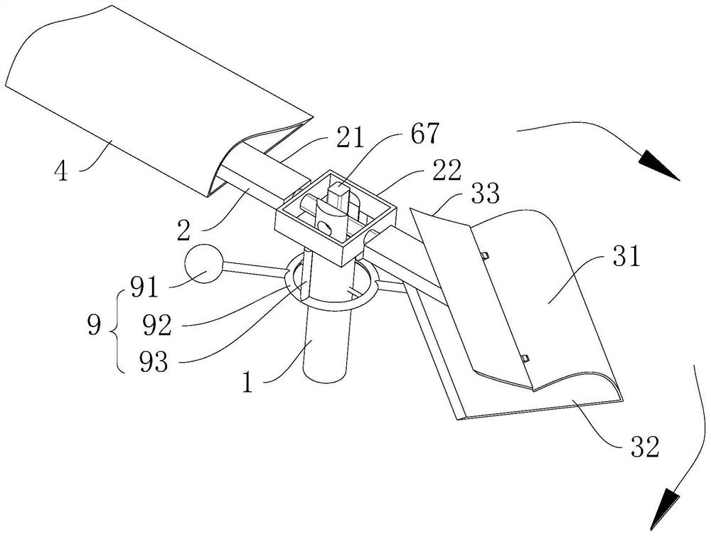
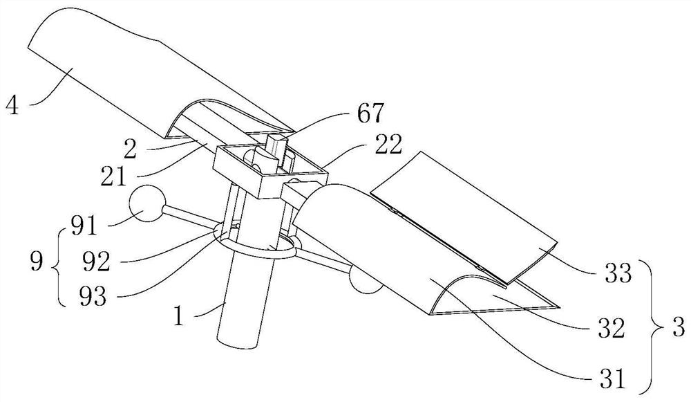
[0055] Please refer to figure 1 , figure 2 and image 3 , a wing assembly is provided for this embodiment, which includes:
[0056] Drive shaft 1, the drive shaft 1 is used to drive the wing to rotate;
[0057] Wing mounting bracket 2, the middle part of wing mounting bracket 2 is connected with the end of driving shaft 1;
[0058] The first blade 3, the first blade 3 is arranged on one side of the wing mounting bracket 2, and the first blade 3 is rotationally connected with the wing mounting bracket 2;
[0059] The second blade 4, the second blade 4 is arranged on the other side of the wing mounting bracket 2;
[0060] The transmission mechanism 6 is installed on the wing mounting bracket 2, and the transmission mechanism 6 drives the first blade 3 to rotate.
[0061] In some embodiments of the present invention, in order to realize that "helicopter" obtains excellent flight performance, the most critical problem is to properly solve the transition from the vertical lif...
Embodiment 2
[0066] Please refer to figure 1 , the present embodiment proposes based on the technical solution of embodiment 1, and also includes an automatic wing balance mechanism 9, and the automatic wing balance mechanism 9 includes a sensing ring 92, two inertial balls 91 and two pushing links 93; the sensing ring 92 includes The circular outer ring and the horizontal shaft connected to the inner wall of the circular outer ring, the horizontal shaft runs through the side wall of the driving shaft 1, and the horizontal shaft is connected to the driving shaft 1 in rotation. Two inertial balls 91 are symmetrically arranged on the circular outer ring. Two push links 93 are arranged symmetrically, and one end of any push link 93 is hinged with the wing mounting bracket 2, and the other end of the push link 93 is hinged with the circular outer ring.
[0067] The wing automatic balancing mechanism is set to drive the wing mounting bracket 2 to swing, the middle part of the wing mounting brac...
Embodiment 3
[0069] Please refer to figure 1 , this embodiment proposes based on the technical solution of Embodiment 1, the first blade 3 is sleeved on the wing mounting bracket 2, the first blade 3 includes a front edge portion 31 and a rear edge portion, and the rear edge portion includes a spreader plate 33, and the fixed plate 32, the expansion plate 33 is hinged with the front edge portion 31, and the fixed plate 32 is connected with the front edge portion 31.
[0070] In some embodiments of the present invention, if the wing mounting bracket 2 is connected to the outer wall of the first blade 3, according to the analysis of aerodynamics, it can be seen that the connection between the blade and the rotor must be fixed under the high-speed rotation of the rotor. Larger resistance is generated, so in order to avoid the above situation, the present embodiment uses the first blade 3 to be sleeved on the wing mounting bracket 2, considering that after the first blade 3 is sleeved on the w...
PUM
 Abstract
Description
Claims
Application Information
 - R&D
- Intellectual Property
- Life Sciences
- Materials
- Tech Scout
- Unparalleled Data Quality
- Higher Quality Content
- 60% Fewer Hallucinations
Browse by: Latest US Patents, China's latest patents, Technical Efficacy Thesaurus, Application Domain, Technology Topic, Popular Technical Reports.
© 2025 PatSnap. All rights reserved.Legal|Privacy policy|Modern Slavery Act Transparency Statement|Sitemap|About US| Contact US: help@patsnap.com


