
Joint beam forming and spatial modulation method based on intelligent reflecting surface and transmitting end

A combined beamforming and spatial modulation technology, applied in the directions of space transmit diversity, diversity/multi-antenna systems, electrical components, etc., can solve the problems of large complexity, limited MIMO antenna array scale, and high beamforming costs, and achieve improved The effect of signal-to-noise ratio, reducing transmission bit error rate and improving system performance

Active Publication Date: 2021-07-13
DONGHUA UNIV
View PDF5 Cites 7 Cited by
  • Summary
  • Abstract
  • Description
  • Claims
  • Application Information

AI Technical Summary

Problems solved by technology

[0005] The purpose of the present invention is to solve the problems of high cost and excessive complexity of traditional beamforming and its limitation on the size of MIMO antenna arrays, and at the same time to further improve the signal-to-noise ratio and reduce the bit error rate

Method used


Image

  • Joint beam forming and spatial modulation method based on intelligent reflecting surface and transmitting end
  • Joint beam forming and spatial modulation method based on intelligent reflecting surface and transmitting end
  • Joint beam forming and spatial modulation method based on intelligent reflecting surface and transmitting end

Examples


Embodiment Construction

[0047] Below in conjunction with specific embodiment, further illustrate the present invention. It should be understood that these examples are only used to illustrate the present invention and are not intended to limit the scope of the present invention. In addition, it should be understood that after reading the teachings of the present invention, those skilled in the art can make various changes or modifications to the present invention, and these equivalent forms also fall within the scope defined by the appended claims of the present application.

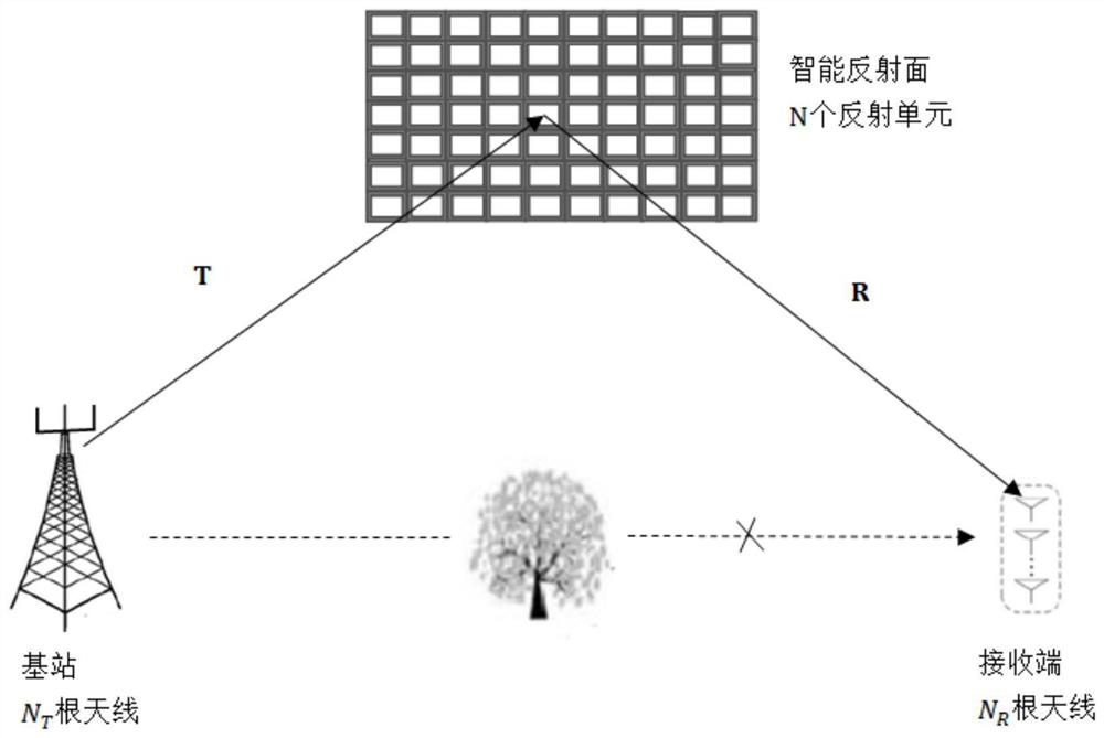
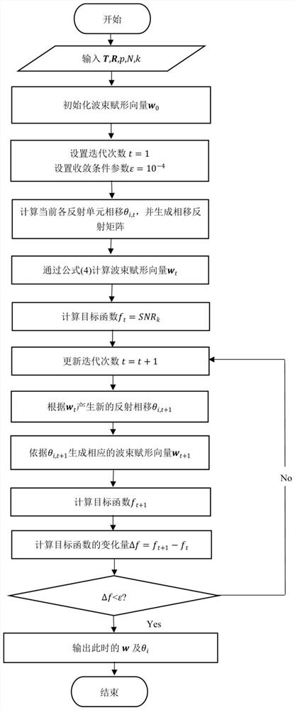
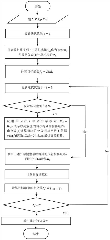
[0048] The present invention proposes a joint beamforming and spatial modulation method (intelligent reflecting surface-joint beamforming and spatial modulation, IRS-JBSM) based on an intelligent reflecting surface-joint beamforming and spatial modulation (IRS-JBSM) for an intelligent reflecting surface-joint MIMO system. Specifically, through the established system The model, based on the spatial modulation at the receiver, us...


PUM


Abstract

The invention relates to a joint beamforming and receiving end spatial modulation method based on an intelligent reflecting surface and a transmitting end. According to the method, the beamforming of the transmitting end and an intelligent reflecting surface angle are optimally designed based on the maximum system receiving signal-to-noise ratio. A greedy detection scheme and a maximum likelihood detection scheme based on exhaustive search are given according to two conditions of continuous phase shift and discrete phase shift of the intelligent reflecting surface. According to the method provided by the invention, spatial modulation is utilized, the problem of inter-channel interference in multi-antenna transmission is effectively avoided, spatial domain resources are fully utilized, and an effective data transmission rate is provided. In addition, joint beam forming on the transmitting end and the intelligent reflecting surface is used, so that the signal quality is improved, and reliable communication is ensured.

Description

technical field [0001] The invention relates to a space modulation and joint beam forming method of an intelligent reflective surface MIMO wireless communication system, belonging to the field of wireless communication. Background technique [0002] The fifth-generation mobile communication (5G) technology has been deployed on a large scale in many countries and regions, which has greatly improved the information transmission rate. The existing large-scale multiple-input multiple-output (Multiple-Input Multiple-Out, MIMO) The large-scale antenna array realizes the transmission and reception of information and increases the power gain; however, the traditional phased array required for beamforming limits the size of the MIMO antenna array due to power consumption and hardware costs, so that the advantages of MIMO technology cannot be effectively obtained. play. [0003] The smart reflector is considered to be a promising alternative technology to the traditional phased array...

Claims


Application Information

Patent Timeline
Patent Type & Authority Applications(China)
IPC IPC(8): H04B7/0413H04B7/06
CPCH04B7/0413H04B7/0617H04B7/0697H04B7/04013
Inventor 吴贇高浩然白恩健蒋学芹
Owner DONGHUA UNIV
Learn More