An automatic welding system, welding method and connection structure of welded products

A technology of automatic welding and welding methods, applied in welding equipment, metal processing equipment, metal processing, etc., can solve the problems of large dependence on manual operation, unfavorable large-scale production, and high labor cost, so as to reduce human dependence and human labor. Dependency, the effect of increasing the level of automation

Active Publication Date: 2022-07-22
SHENZHEN TIMEYAA ELECTRONIC TECH CO LTD
View PDF0 Cites 0 Cited by
  • Summary
  • Abstract
  • Description
  • Claims
  • Application Information

AI Technical Summary

Problems solved by technology

[0004] In view of the above-mentioned related technologies, the inventor believes that the soldering equipment in the related technologies relies heavily on manual operations, which is not conducive to large-scale production, and the labor cost is relatively high

Method used


Image

  • An automatic welding system, welding method and connection structure of welded products
  • An automatic welding system, welding method and connection structure of welded products
  • An automatic welding system, welding method and connection structure of welded products

Examples


Embodiment 1

[0061] The embodiments of the present application disclose an automatic welding system and a welding method.

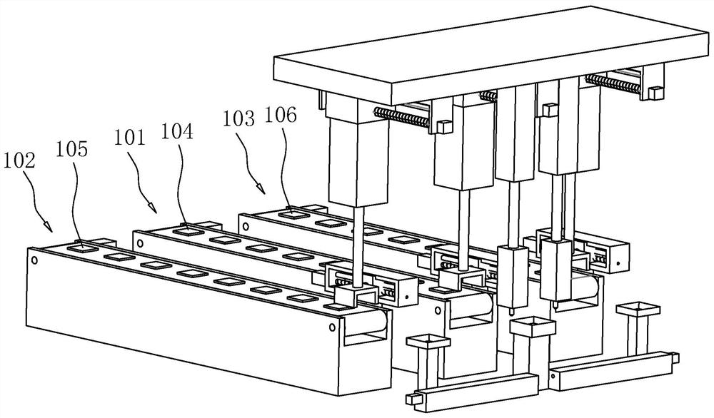
[0062] like figure 1 , 2 As shown, an automatic welding system includes a detection unit, a control unit and three parallel conveying lines, including a first transmission line 101, a second transmission line 102 is arranged on one side of the first transmission line 101, and a first transmission line 102 is arranged on the other side. Three transmission lines 103 , the first transmission line 101 , the second transmission line 102 , and the third transmission line 103 are parallel to each other and have the same structure.

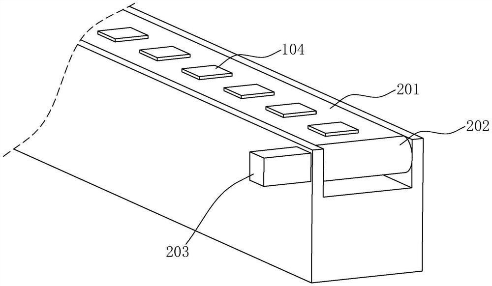
[0063] like image 3 As shown, this embodiment takes the first transmission line 101 as an example. The first transmission line 101 includes a first conveyor belt 201, and the first conveyor belt 201 is driven by two first rollers 202. The drive motor 203 is controlled by the control unit, including speed control, on or off control.

[0064] ...

Embodiment 2

[0115] The embodiment of the present application discloses a connection structure of a welded product obtained by an automatic welding system.

[0116] like Figure 10 , 11 As shown, a connection structure of a welded product obtained by an automatic welding system includes pins 902 arranged on the atomizer housing 901, the direction of the pins 902 is parallel to the length direction of the atomizer housing 901, and the first welding part The plane where 104 is located is parallel to the pin 902, a contact point 904 is provided on the lower surface of the first welding part 104, and a snap-fit ​​assembly 903 is provided between the contact point 904 and the pin 902, so that the first welding part 104 is connected to the atomizer. The device housings 901 can be snap-connected through a snap-fit ​​assembly 903 .

[0117] The first welding part 104 , the second welding part 105 and the third welding part 106 are welded products obtained by the welding process as described in Emb...


PUM


Abstract

The present application relates to an automatic welding system, comprising a first conveying line and a second conveying line; the first conveying line includes a first conveying belt for conveying a first welding piece, and one end of the first conveying belt in the conveying direction is provided with a first conveying belt. A pallet, a first clamp for conveying the first welding piece from the first to grasping and placing on the first pallet is arranged between the first pallet and the first conveying belt; the second conveying line includes a first clamp for conveying the second welding piece The second conveyor belt is provided with a second carrier on one end of the second conveyor belt in the conveying direction. The effect of the present application: the present application conveys two welding parts through a two-way conveying line, and respectively grabs the first welding part and the second welding part onto the first support and the second support through the first clamp and the second clamp, Then, the two welded parts are welded between the first bracket and the second bracket, which improves the degree of automation, reduces the degree of human dependence, and is more suitable for mass production. Thereby improving production efficiency.

Description

technical field [0001] The present application relates to the field of welding technology, and in particular, to an automatic welding system, a welding method and a connection structure of welded products. Background technique [0002] Welding is known as a mechanical tailor who is responsible for welding stamped workpieces together. It is widely used in manufacturing. Welding is a manufacturing process and technology that joins metals or other thermoplastic materials such as plastics by heating, high temperature or high pressure. . [0003] In the related art, when the PCB board is welded in the PCB processing process, two PCB boards are generally placed under the welding machine manually, aiming at the welding gun of the welding machine, and the welding gun is punched downward to solder the two PCBs or between the PCB and the cable. thus connecting. [0004] In view of the above-mentioned related technologies, the inventors believe that the soldering equipment in the rel...

Claims


Application Information

Patent Timeline
Patent Type & Authority Patents(China)
IPC IPC(8): B23K3/00B23K3/08
CPCB23K3/00B23K3/08
Inventor 刘金鑫首召兵
Owner SHENZHEN TIMEYAA ELECTRONIC TECH CO LTD
Why Eureka
Try Eureka