Machine tool machining system based on intelligent control

A processing system and intelligent control technology, applied in the direction of manufacturing tools, metal processing equipment, metal processing machinery parts, etc., can solve the problems of loose workpiece clamping, low efficiency of workpiece loading and positioning, low positioning accuracy, etc., to achieve Improving machining accuracy, ensuring stability, and reliable machining effects

Pending Publication Date: 2021-07-16
佛山市精弗斯智能制造有限公司
View PDF1 Cites 0 Cited by
  • Summary
  • Abstract
  • Description
  • Claims
  • Application Information

AI Technical Summary

Problems solved by technology

[0003] Such as CN104527288B prior art discloses a bed body of a machine tool and a production and processing system with the bed body of the machine tool. Due to the use of manual positioning and manual clamping, it is time-consuming and labor-intensive, and the labor intensity of the workman is large and the loading and Positioning efficiency is low
Because manual positioning is greatly affected by human factors, there may be deviations every time the workpiece is positioned, and the stability and consistency of workpiece positioning cannot be maintained. Therefore, the positioning accuracy is low, which will cause serious problems to the processing quality of the workpiece to be processed. Large adverse effects, thereby adversely affecting product yield
[0004] In order to solve the common problems in the field that the workpiece is not tightly clamped, the processing tool head cannot be replaced, the processing tool replacement efficiency is low, the labor intensity is high, and the monitoring of the processing process is lacking, etc., the present invention is made

Method used


Image

  • Machine tool machining system based on intelligent control
  • Machine tool machining system based on intelligent control
  • Machine tool machining system based on intelligent control

Examples


Embodiment Construction

[0034] The following will clearly and completely describe the technical solutions in the embodiments of the present invention with reference to the accompanying drawings in the embodiments of the present invention. Obviously, the described embodiments are only part of the embodiments of the present invention, not all of them. Based on the embodiments of the present invention, all other embodiments obtained by persons of ordinary skill in the art without creative efforts fall within the protection scope of the present invention.

[0035]It should be noted that if there is a directional indication (such as up, down, left, right, front, back...) in the embodiment of the present invention, the directional indication is only used to explain the position in a certain posture (as shown in the accompanying drawing). If the specific posture changes, the directional indication will also change accordingly.

[0036] In addition, if there are descriptions involving "first", "second" and s...


PUM


Abstract

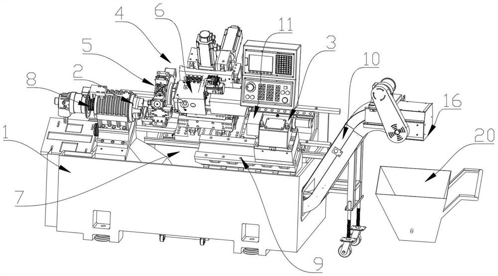
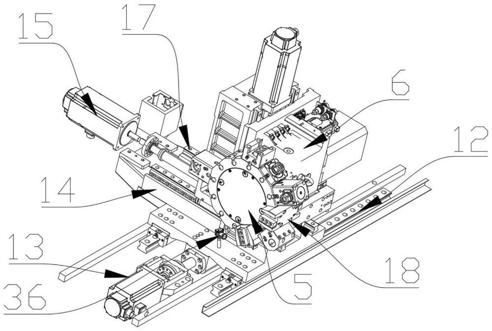
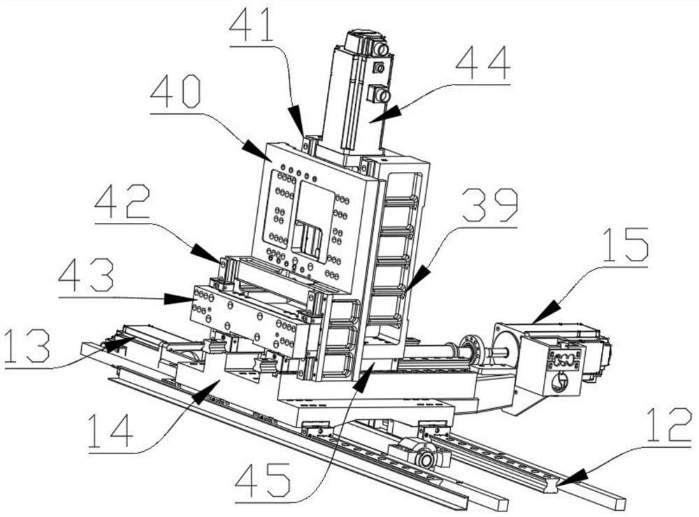
The invention discloses a machine tool machining system based on intelligent control. The machine tool machining system involves a supporting seat, a machining tool magazine, a tail top, a clamping mechanism, a first offset mechanism, a second offset mechanism, a third offset mechanism, a fourth offset mechanism and a monitoring device, wherein the first offset mechanism, the second offset mechanism and the third offset mechanism are all arranged on the upper top of the supporting seat, the first offset mechanism, the second offset mechanism and the third offset mechanism are vertically and slidably connected in pairs, the third offset mechanism comprises a third sliding rail, an auxiliary rail, a third driving mechanism, a first L-shaped seat, a second L-shaped seat, an offset seat and a supporting plate, the offset seat is slidably connected with the second offset mechanism, the third offset rail is vertically and fixedly connected with the upper top of the offset seat, and the third sliding rail and the auxiliary rail are arranged on the two sides of the second L-shaped seat. The structure of the machining system effectively solves the technical problems existing in the field of machine tools, and has the advantages of being high in tool replacement efficiency, high in machining stability and practical.

Description

technical field [0001] The invention relates to the technical field of numerical control machine tools, in particular to a machine tool processing system based on intelligent control. Background technique [0002] Machine tools are the foundation of industry, and any industrial manufacturing production is inseparable from machine tools. The precision and development level of machine tools determine the industrial level of a country, so it is very important to improve the precision and level of machine tools. An important aspect that reflects the level of the machine tool is whether the machine tool itself can control the processing process and monitor the processing performance of the machine tool itself, and process the monitored information in a timely manner, and take effective measures to ensure the safety, reliability and quality of processing. [0003] Such as CN104527288B prior art discloses a bed body of a machine tool and a production and processing system with the ...

Claims


Application Information

Patent Timeline
IPC IPC(8): B23Q3/155B23Q3/06B23B23/00B23Q17/22B23Q11/00
CPCB23B23/00B23Q3/06B23Q3/155B23Q11/0042B23Q17/2233
Inventor 彭永生
Owner 佛山市精弗斯智能制造有限公司
Why Eureka
Try Eureka