Scrap collecting device for milling machine workbench

A workbench and debris collection technology, which is applied to milling machine equipment, milling machine equipment details, manufacturing tools, etc., can solve the problems of inconvenient cleaning of debris, achieve the effects of improving friction, alleviating inlet blockage, and improving collection effect

Inactive Publication Date: 2021-07-16
王小梅
View PDF8 Cites 0 Cited by
  • Summary
  • Abstract
  • Description
  • Claims
  • Application Information

AI Technical Summary

Problems solved by technology

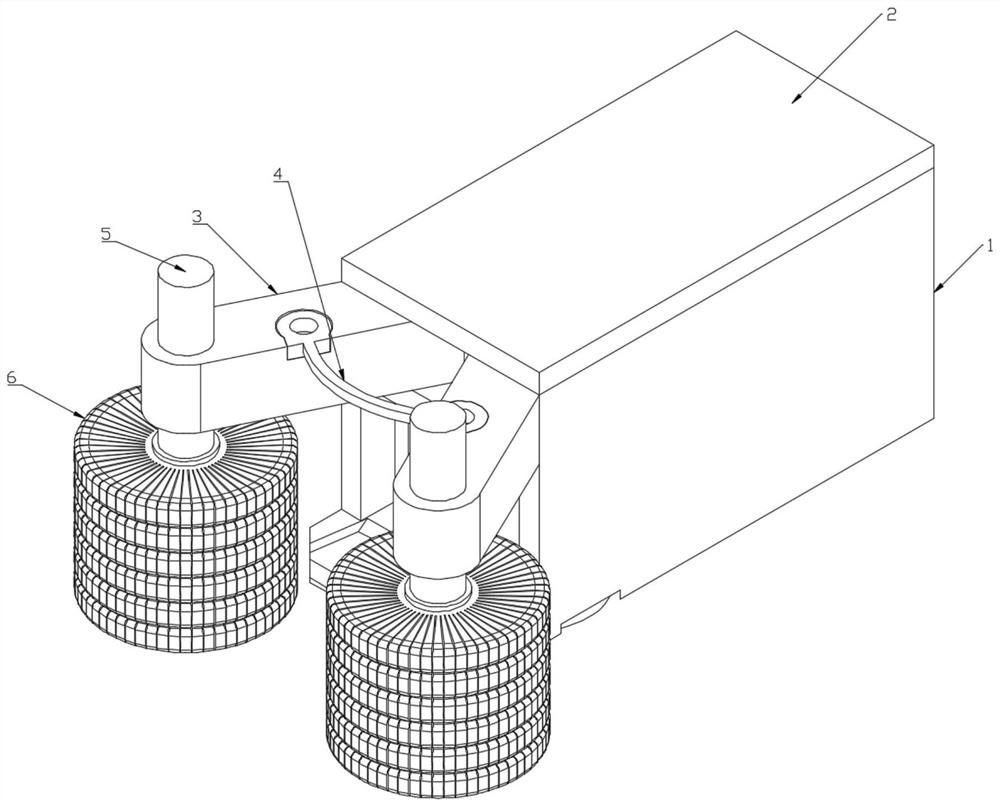
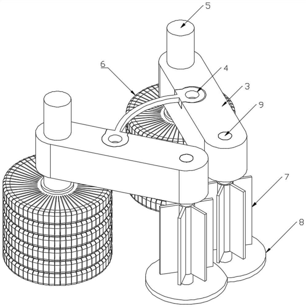
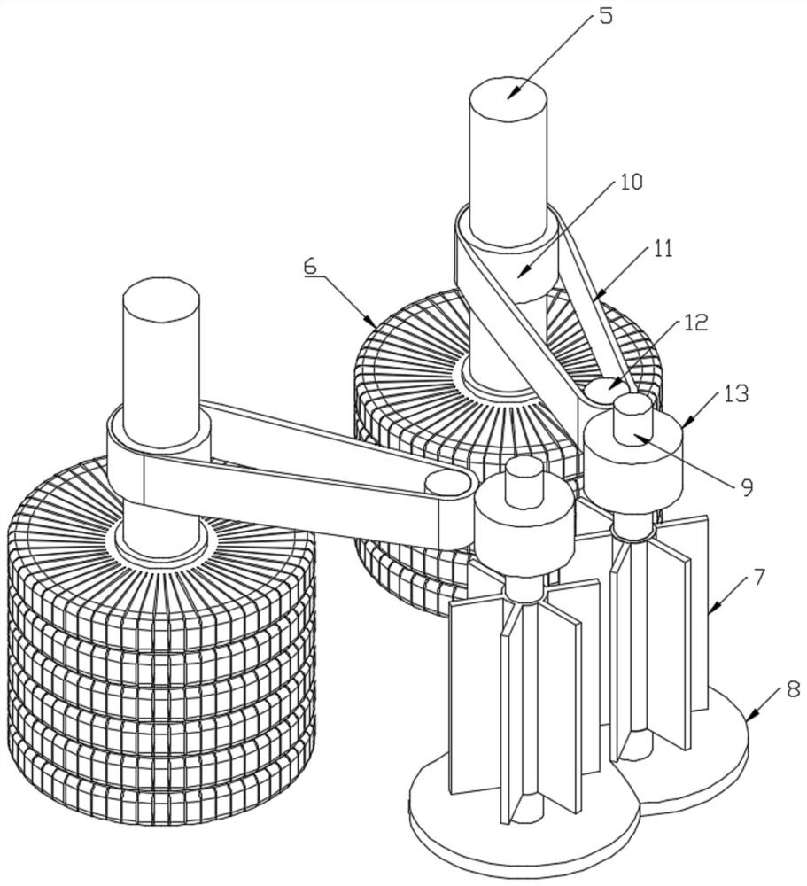
[0003] The object of the present invention is to provide a chip collecting device for the workbench of a milling machine. By pushing the placed chip collecting device to move to the side where the brush body is provided, the friction transmission part installed on the bottom surface of the box body will rub against the groove to rotate to the outside, and the rotating The friction transmission part drives the installed two brushes to rotate inwards through the transmission part, which facilitates the accumulation of debris and solves the problem that the debris in the groove of the existing workbench is not easy to clean

Method used


Image

  • Scrap collecting device for milling machine workbench
  • Scrap collecting device for milling machine workbench
  • Scrap collecting device for milling machine workbench

Examples


Embodiment Construction

[0029] The following will clearly and completely describe the technical solutions in the embodiments of the present invention with reference to the accompanying drawings in the embodiments of the present invention. Obviously, the described embodiments are only some, not all, embodiments of the present invention. Based on the embodiments of the present invention, all other embodiments obtained by persons of ordinary skill in the art without creative efforts fall within the protection scope of the present invention.

[0030] In describing the present invention, it is to be understood that the terms "opening", "upper", "lower", "thickness", "top", "middle", "length", "inner", "surrounding" etc. Indicating orientation or positional relationship is only for the convenience of describing the present invention and simplifying the description, and does not indicate or imply that the components or elements referred to must have a specific orientation, be constructed and operated in a sp...


PUM


Abstract

The invention discloses a scrap collecting device for a milling machine workbench, and relates to the technical field of milling machine auxiliary equipment. The scrap collecting device comprises a box body, a cavity with a groove opening is formed in the box body, an inlet communicating with the cavity is formed in one side face of the box body, an open groove is formed in the box body, a bottom groove communicating with the outer side is formed in the bottom face of the box body, and the bottom groove and the open groove are distributed correspondingly. Two supporting arms extending outwards are rotationally installed in the bottom groove and connected through an elastic piece, and a cylinder is rotationally installed at the tail end of each supporting arm. A friction transmission part is installed at the inlet of the box body and drives the installed cylinders to rotate through a transmission component, and a brush body is installed at the bottom of each cylinder. According to the scrap collecting device, the placed scrap collecting device is pushed to move towards the side provided with the brush bodies, the friction transmission part installed on the bottom face of the box body and a groove generate friction rotation, the rotating friction transmission part drives the two installed brush bodies to rotate towards the inner side through the transmission component, and scrap gathering is conveniently achieved.

Description

technical field [0001] The invention belongs to the technical field of milling machine auxiliary equipment, in particular to a chip collecting device for a milling machine table. Background technique [0002] Milling machines are known for their high machining accuracy and high machining efficiency, but a lot of chips are produced during the machining process. The traditional method is still used to clean these chips, which is to let the chips pile up continuously until the operator of the milling machine removes them when he is off work. Take time out for cleaning in advance: When the milling machine operator cleans debris and dirt on the surface of the parts, he uses a high-pressure air gun to blow the debris and dirt around, which not only causes pollution to the ground and the milling machine, but also poses a safety hazard. The debris is easy to Fly into the eyes of the operator; therefore, the existing cleaning methods will seriously affect the sanitation inside the la...

Claims


Application Information

Patent Timeline
Patent Type & Authority Applications(China)
IPC IPC(8): B23Q11/00B23C9/00
CPCB23Q11/00B23Q11/0042B23C9/00
Inventor 王小梅
Owner 王小梅
Why Eureka
Try Eureka