
Testing device suitable for parts of electric tool

A technology of testing equipment and electric tools, which is applied in the testing of mechanical components, testing of machine/structural components, workpiece clamping devices, etc., can solve the problem of stuck or inflexible adjustment, reduce flexibility and stability, and reduce the test area and other problems to achieve the effect of avoiding stuck or inflexible adjustment, improving flexibility and stability, and increasing flexibility and stability

Inactive Publication Date: 2021-07-16
东莞市顺英机电设备有限公司
View PDF0 Cites 0 Cited by
  • Summary
  • Abstract
  • Description
  • Claims
  • Application Information

AI Technical Summary

Problems solved by technology

[0002] Electric tools used cast iron as the shell at first, and then changed to aluminum alloy as the shell. In the 1960s, thermoplastic engineering plastics were applied to electric tools, and realized double insulation of electric tools, which ensured the safety of electric tools. The test device is required for processing. 1. When using the existing electric tool test device, the flexibility and stability of adjusting the test direction when the test body is used is reduced during the rotation process, and it is easy to get stuck when adjusting the test direction Or the adjustment is inflexible, which reduces the high efficiency and quickness of the test direction rotation; 2. When the existing power tool test device is used, the test board is prone to tilt or offset when the test height is adjusted, which reduces the use of the test subject. The flexibility and stability of adjusting the test height at any time; 3. When using the existing electric tool test device, the test area is reduced, and the flexibility and convenience of adjusting different objects under test are also reduced, so that the test subject can use There is no variability, which reduces the test efficiency. Therefore, we propose a new test device for electric tool parts

Method used


Image

  • Testing device suitable for parts of electric tool
  • Testing device suitable for parts of electric tool
  • Testing device suitable for parts of electric tool

Examples


Embodiment 1

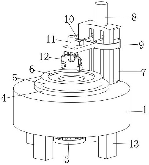
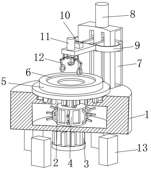
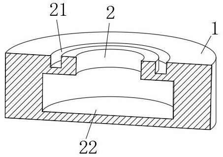
[0031]A test device suitable for power tool components such as Figure 1-2 As shown, the test body 1 is included, the upper middle part of the test body 1 is provided with a sliding groove 2, the lower end middle part of the test body 1 is fixedly connected with a motor 3, the output end of the motor 3 penetrates the test body 1 and is fixedly connected with a sliding structure 4, and the sliding The upper end of the structure 4 is fixedly connected with a storage board 5, and the middle part of the upper end of the storage board 5 is provided with a test slot 6, and the rear part of the upper end of the test body 1 is fixedly connected with a support frame 7, and the upper end of the support frame 7 is fixedly connected with a telescopic controller 8 , the output end of the No. 1 telescopic controller 8 runs through the upper end of the support frame 7 and is fixedly connected with an adjustment structure 9. The adjustment structure 9 is provided with a test controller 10 and ...

Embodiment 2

[0034] On the basis of Example 1, as Figure 3-4 As shown, a test device suitable for electric tool components includes a test body 1, a sliding groove 2 is opened in the middle of the upper end of the test body 1, a motor 3 is fixedly connected to the middle of the lower end of the test body 1, and the output end of the motor 3 runs through The test main body 1 is fixedly connected with a sliding structure 4, the upper end of the sliding structure 4 is fixedly connected with a storage board 5, the middle part of the upper end of the storage board 5 is provided with a test slot 6, and the upper end rear of the test main body 1 is fixedly connected with a support frame 7, supporting The upper end of the frame 7 is fixedly connected with a No. 1 telescopic controller 8. The output end of the No. 1 telescopic controller 8 runs through the upper end of the support frame 7 and is fixedly connected with an adjustment structure 9. The adjustment structure 9 is provided with a test con...

Embodiment 3

[0037] On the basis of Example 1, as Figure 5 with 6 As shown, a test device suitable for electric tool components includes a test body 1, a sliding groove 2 is opened in the middle of the upper end of the test body 1, a motor 3 is fixedly connected to the middle of the lower end of the test body 1, and the output end of the motor 3 runs through The test main body 1 is fixedly connected with a sliding structure 4, the upper end of the sliding structure 4 is fixedly connected with a storage board 5, the middle part of the upper end of the storage board 5 is provided with a test slot 6, and the upper end rear of the test main body 1 is fixedly connected with a support frame 7, supporting The upper end of the frame 7 is fixedly connected with a No. 1 telescopic controller 8. The output end of the No. 1 telescopic controller 8 runs through the upper end of the support frame 7 and is fixedly connected with an adjustment structure 9. The adjustment structure 9 is provided with a te...


PUM


Abstract

The invention discloses a testing device suitable for parts of an electric tool. The testing device comprises a testing body, the output end of a motor penetrates through the testing body and is fixedly connected with a sliding structure, the upper end of the sliding structure is fixedly connected with a placement plate, the rear part of the upper end of the testing body is fixedly connected with a supporting frame, the upper end of the supporting frame is fixedly connected with a first telescopic controller, the output end of the first telescopic controller penetrates through the upper end of the supporting frame and is fixedly connected with an adjusting structure, and the output end of the second telescopic controller penetrates through the adjusting structure and is fixedly connected with a testing structure. According to the testing device suitable for the parts of the electric tool, the phenomenon of jamming or inflexible adjustment when the testing direction is adjusted is avoided, the high efficiency and rapidness of rotation in the testing direction are improved, the flexibility and stability of adjusting the testing height when the testing body is used are improved, and the flexibility and convenience of adjusting different objects to be tested are improved while a test area is increased.

Description

technical field [0001] The invention relates to the technical field of electric tool processing, in particular to a test device suitable for electric tool components. Background technique [0002] Electric tools used cast iron as the shell at first, and then changed to aluminum alloy as the shell. In the 1960s, thermoplastic engineering plastics were applied to electric tools, and realized double insulation of electric tools, which ensured the safety of electric tools. The test device is required for processing. 1. When using the existing electric tool test device, the flexibility and stability of adjusting the test direction when the test body is used is reduced during the rotation process, and it is easy to get stuck when adjusting the test direction Or the adjustment is inflexible, which reduces the high efficiency and quickness of the test direction rotation; 2. When the existing power tool test device is used, the test board is prone to tilt or offset when the test heig...

Claims


Application Information

Patent Timeline
Patent Type & Authority Applications(China)
IPC IPC(8): B25H1/10B25B11/00G01M13/00
CPCB25B11/00B25H1/10G01M13/00
Inventor 邓良光李联庆闫静
Owner 东莞市顺英机电设备有限公司
Learn More