Self-regulating type photobioreactor

A photobioreactor, self-regulating technology, applied in the direction of photobioreactor, bioreactor/fermenter combination, bioreactor/fermenter for specific purposes, etc. The problem of high growth temperature can reduce the irradiation, prevent the reaction, and improve the growth efficiency.

Inactive Publication Date: 2021-07-16
海南欧瑞康健康管理有限公司
View PDF31 Cites 0 Cited by
  • Summary
  • Abstract
  • Description
  • Claims
  • Application Information

AI Technical Summary

Problems solved by technology

[0002] Photobioreactors are used to cultivate microorganisms that require light conditions to reproduce and respond to light. During the day, the sun provides light to the cultures. In order to improve the efficiency of light, the angle of light received by the equipment is controlled by photosensitive equipment. However, in the case of strong sunlight in summer, the intensity of light received inside the reactor is too hi

Method used


Image

  • Self-regulating type photobioreactor
  • Self-regulating type photobioreactor
  • Self-regulating type photobioreactor

Examples


Embodiment 1

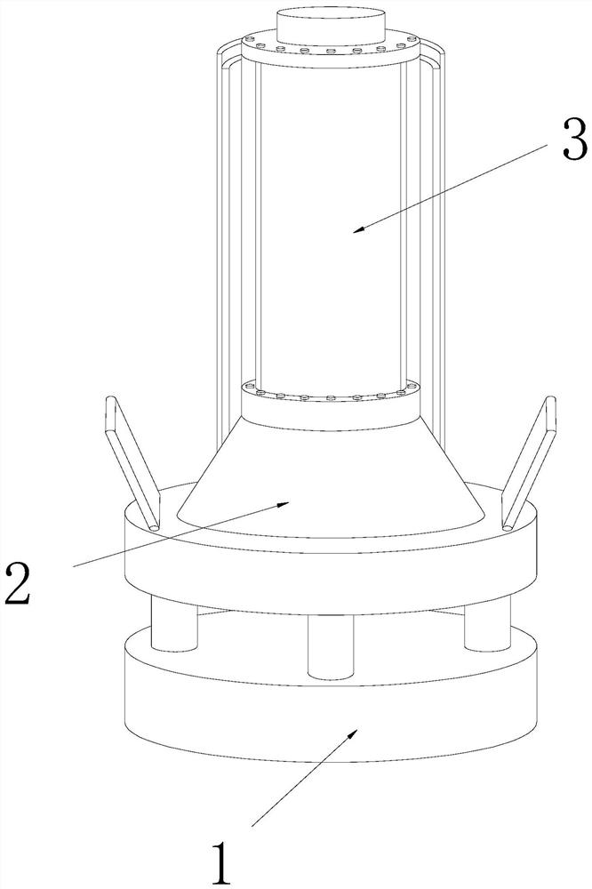
[0028] as attached figure 1 To attach Figure 6 Shown:

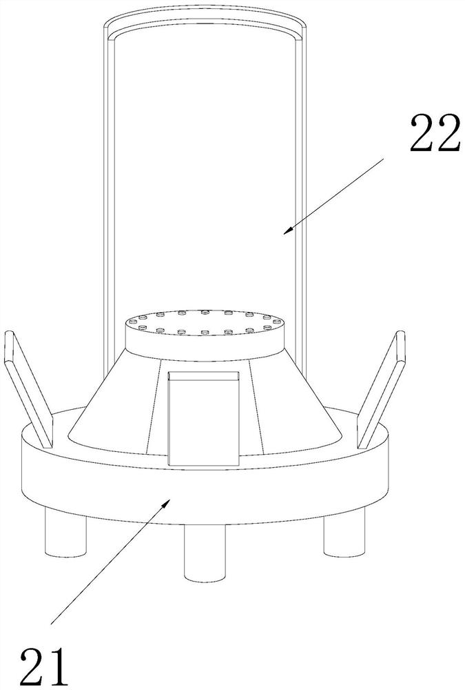
[0029] The invention provides a self-regulating photobioreactor, the structure of which includes a base 1, a light adaptation device 2, and a reaction chamber 3, the upper side of the base 1 is embedded and connected with the lower side of the light adaptation device 2, and the light adaptation device 2. The middle part of the upper end is bonded to the lower side of the reaction chamber 3. The light adaptation device 2 includes an adjuster 21 and a dimming device 22. The lower side of the adjuster 21 is embedded and connected to the upper side of the base 1. The dimming device 22 is embedded and connected with the regulator 21 upper side.

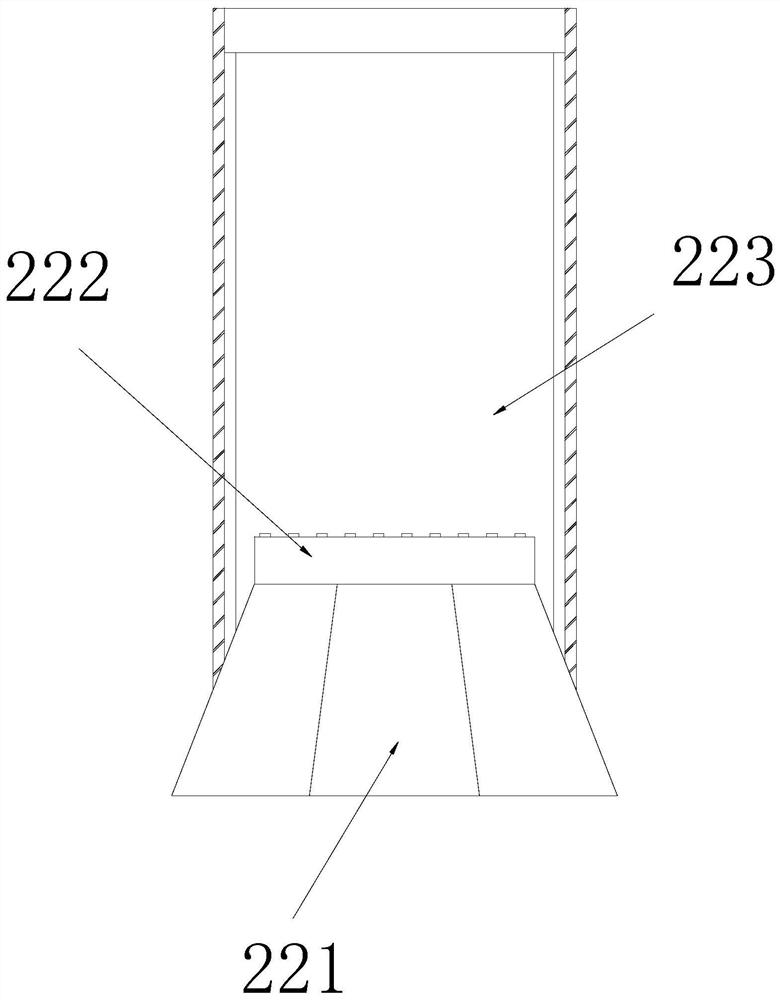
[0030] Wherein, the dimming device 22 includes an adjusting base 221, a fixing base 222, and a shade 223. Side screw connection, the lower side of the light shield 223 is connected with the inner shaft of the adjustment base 221, the length of the light shield 223 is 1.5 times the...

Embodiment 2

[0037] as attached Figure 7 to attach Figure 9 Shown:

[0038] Wherein, the adjuster 21 includes a fixed cover 211, a spring seat 212, a battery 213, and a shutter 214. The upper side of the middle part of the fixed cover 211 is bonded to the lower side of the dimming device 22. The lower side of the fixed cover 211 is welded and connected, the outer side of the battery 213 is interference-fitted with the inner side of the fixed cover 211, the lower end of the shutter 214 is axially connected to the upper end of the fixed cover 211, and the shutters 214 are installed obliquely, and the number is four , with the battery 213 as the center in a circular distribution, so that the photosensitive housing 21a can be shielded by the photosensitive housing 21a around, preventing the backlight surface of the photosensitive housing 21a from being illuminated by ambient reflected light.

[0039] Wherein, the shutter 214 includes a reset plate 14a, a top plate 14b, a sealing block 14c,...


PUM


Abstract

The invention discloses a self-regulating type photobioreactor. The self-regulating type photobioreactor structurally comprises a base, a light adaptation device and a reaction chamber, wherein the upper side of the base and the lower side of the light adaptation device are in built-in connection, and the middle part of the upper end of the light adaptation device is bonded to the lower side of the reaction chamber. A spring is compressed by a magnetic-attracted iron slab, moves upwards under the fixing of a guide post and will drive a light shield for regulation while moving, a folded sheet is spread due to drawing of an offset plate so as to shield part of light, an internal temperature of the reaction chamber is prevented from increasing in case of intense light, the growth efficiency of organisms is increased, the magnetic mutual attraction is improved after an electromagnet is regulated, a link drives an ejector pin to move upwards, the ejector pin extrudes a top plate at the bottom of a shield after moving upwards, the top plate drives a baffle to offset after the top plate is extruded so as to shield a photosensitive shell, the irradiation of ambient light to the photosensitive shell is reduced, and photosensitive control is prevented from reaction on the ambient light.

Description

technical field [0001] The invention belongs to the field of bioreactors, and more specifically relates to a self-regulating photobioreactor. Background technique [0002] Photobioreactors are used to cultivate microorganisms that require light conditions to reproduce and respond to light. During the day, the sun provides light to the cultures. In order to improve the efficiency of light, the angle of light received by the equipment is controlled by photosensitive equipment. However, in the case of strong sunlight in summer, the intensity of light received inside the reactor is too high, which will easily lead to excessive growth temperature of microorganisms inside the reactor, reducing the growth efficiency of microorganisms, and at the same time, high-intensity light will easily lead to photosensitivity on the backlight surface. The board receives the reflected light from the environment, which causes the function of the device to control the deflection angle through the ...

Claims


Application Information

Patent Timeline
IPC IPC(8): C12M1/36C12M1/00
CPCC12M21/02C12M41/06
Inventor 张小军
Owner 海南欧瑞康健康管理有限公司
Why Eureka
Try Eureka