Drainage hidden type metal tile and metal tile machining die

A technology for processing molds and metal tiles, which is applied in the field of drainage hidden metal tiles and metal tile processing molds, which can solve the problems of affecting the aesthetics of buildings, falling icicles, and the impact of pedestrians, achieving better collection effects and convenient demoulding Effect

Inactive Publication Date: 2021-07-16
杭州金星铜世界装饰材料有限公司 +1
View PDF9 Cites 0 Cited by
  • Summary
  • Abstract
  • Description
  • Claims
  • Application Information

AI Technical Summary

Problems solved by technology

[0004] Regarding the above-mentioned related technologies, since the roof is a slope structure, when it rains, the rainwater flows out from the eaves of the bottom tiles, and the rainwater is concentrated and exported. If the exposed drainage ditch is set under the tiles according to the general architectural design, the drainage ditch affect the aesthetics of the entire building
If there is no drainage ditch, in winter, when the snow melts, a large amount of snow will fall, which will affect pedestrians, and the icicles on the edge of the tile surface may also fall and cause safety hazards

Method used


Image

  • Drainage hidden type metal tile and metal tile machining die
  • Drainage hidden type metal tile and metal tile machining die
  • Drainage hidden type metal tile and metal tile machining die

Examples


Embodiment 1

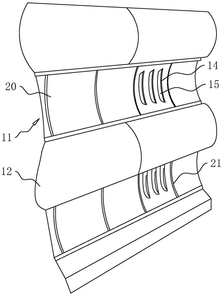
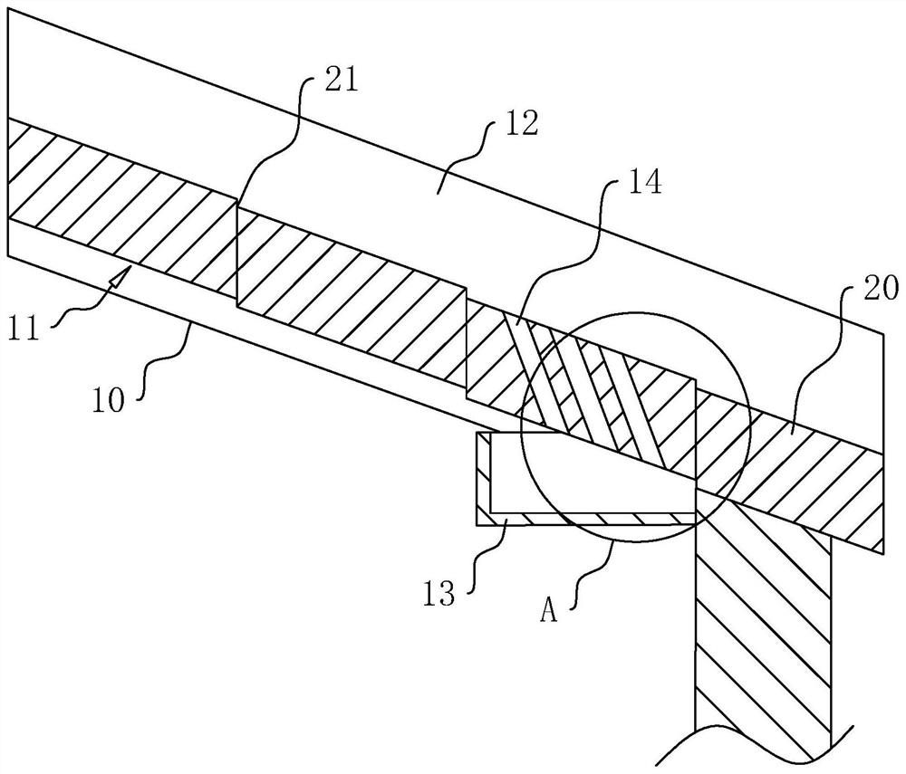
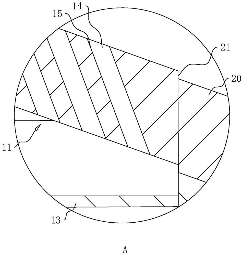
[0038] Embodiment 1: refer to figure 1 and figure 2 , comprising a pre-paved keel frame 10, on which a bottom tile 11 and a cover tile 12 are laid to form a slope. Bottom tiles 11 and cover tiles 12 are arranged alternately, and several groups are arranged along the direction of the keel frame 10 . The bottom tile 11 is lower than the cover tile 12 and is used to guide rainwater from the bottom of the slope. The bottom tile 11 is provided with a drainage groove 14, and the keel frame 10 is provided with an underground ditch 13. The bottom of the drainage groove 14 is projected vertically in the underground ditch 13, and is used to guide the rainwater on the bottom tile 11 into the underground ditch 13.

[0039] When rainwater dripped, because the bottom tile 11 upper surface was concave from both sides to the middle part, the rainwater flowed downward along the slope into the drainage groove 14, and then flowed into the dark ditch 13 from the drainage groove 14, and finally...

Embodiment 2

[0045] The difference between embodiment 2 and embodiment 1 is: refer to Figure 4 , in order to improve the water guiding effect, the bottom tile 11 is fixedly equipped with a water retaining part 30, and there are several water retaining parts 30, which are respectively located at the side of the drainage groove 14 near the lower end of the slope. The water blocking portion 30 forms a blocking surface 31 near the upper end of the slope, and the blocking surface 31 is perpendicular to the position where it is connected to the bottom tile 11 .

[0046] The implementation principle of a water-conducting metal tile in the embodiment of the present application is as follows: when the amount of rainwater is large, the rainwater flows down through the slope, and when it reaches the notch of the drainage groove 14, due to inertia, it continues to impact downward, and when the drainage groove 14 is close to the slope A water retaining part 30 is arranged on one side of the lower end ...

Embodiment 3

[0048] The difference between embodiment 3 and embodiment 1 is: refer to Figure 5 , similarly, in order to improve the water guiding effect, a water storage part 40 is fixedly installed on the bottom tile 11, the water storage part 40 is located on the side of the bottom tile 11 inclined downward, and the upper surface of the water storage part 40 is concave, and it is along the horizontal direction Incline upwards to form a water storage area 41 for temporary water storage. In order to achieve the effect of drainage, the upper end of the water storage part 40 is higher than the drainage groove 14 located at the lowermost end.

[0049] The implementation principle of a water-conducting metal tile in the embodiment of the present application is as follows: when the rainfall is too large and the drainage tank 14 cannot be completely discharged, part of the rainwater is left along the slope, first accumulated in the water storage part 40, and when the water storage part 40 When...


PUM


Abstract

The invention relates to a drainage hidden type metal tile and a metal tile machining die. The drainage hidden type metal tile comprises bottom tiles and cover tiles, wherein the bottom tiles and the cover tiles are arranged on a keel frame, a plurality of groups of cover tiles are arranged in the keel frame direction at intervals, the bottom tiles are arc-shaped plates with upward inner cambered surface, a plurality of groups of bottom tiles are arranged in the keel frame direction at intervals, the cover tiles are respectively located between every two adjacent groups of bottom tiles, drainage grooves are formed in the bottom tiles, an acute angle is formed between the forming direction of the drainage grooves and the water flow direction, flow guide surfaces are formed on the groove walls of the sides, close to the upper end of a slope surface, of the drainage grooves, a blind ditch is formed in the keel frame, and the bottoms of the drainage grooves are projected in the blind ditch. According to the drainage hidden type metal tile, potential safety hazards caused by formation of icicle strips at the edge of the tile surfaces can be reduced.

Description

technical field [0001] The present application relates to the field of roof drainage technology, in particular to a drainage concealed metal tile and a metal tile processing mold. Background technique [0002] Traditional tiled roofs mostly use magnetic tiles and terracotta tiles. Metal tiles are a special tile structure. Compared with magnetic tiles and terracotta tiles, although the cost of metal tiles is higher, they are bright in color, exquisite in shape, majestic and durable, especially suitable for some cultural relics buildings and Landscape Architecture. [0003] Referring to the figure, the current roof structure usually includes a pre-paved keel frame, bottom tiles and cover tiles arranged on the keel frame. There are several groups at intervals in the direction of the dragon frame, the outer arc of the cover tiles is facing upwards, and several groups of cover tiles are arranged at intervals along the direction of the dragon frame, which are respectively locate...

Claims


Application Information

Patent Timeline
Patent Type & Authority Applications(China)
IPC IPC(8): E04D1/06E04D13/04B22C9/22
CPCE04D1/06E04D13/04E04D13/0445B22C9/22
Inventor 朱炳新朱帅奇肖金亮
Owner 杭州金星铜世界装饰材料有限公司
Why Eureka
Try Eureka