
Water tank water feeding automatic control and oscillation anti-freezing device and method

A technology of antifreeze device and control method, which is applied in the direction of non-electric variable control, control/regulation system, and simultaneous control of multiple variables, etc., which can solve problems such as high labor intensity, increased investment cost, and limited inspection intensity, and achieve easy relocation Transportation, high degree of automation, and the effect of improving convenience

Pending Publication Date: 2021-07-16
CHINA PETROLEUM & CHEM CORP +1
View PDF2 Cites 1 Cited by
  • Summary
  • Abstract
  • Description
  • Claims
  • Application Information

AI Technical Summary

Problems solved by technology

[0004] 1. Manual inspection is limited by inspection intensity. Under special circumstances, rapid changes in the level of the water tank caused by changes in water volume cannot be detected in time, which will cause water to flow out of the water tank or the liquid level of the water tank to be low.
[0005] 2. During winter use, a large amount of water resources are wasted due to the passive discovery of ice in the water pipeline and subsequent treatment.
[0006] 3. The inspection intensity of the employees is high, and the processing steps after the pipeline is found to be frozen are labor-intensive
This patent requires the necessary condition of the magnetic pipe wall. If the pipe (pipe network) itself is made of iron, the wall of the pipe (pipe network) can be used as the wall of the magnetic pipe. If the pipe itself is not made of iron, it needs to be installed. Cylindrical high-permeability body, on which the induction heating coil is closely wound as the wall of the permeable tube, which greatly increases the investment cost and reduces the scope of use

Method used


Image

  • Water tank water feeding automatic control and oscillation anti-freezing device and method

Examples


Embodiment Construction

[0027] In order to make the above and other objects, features and advantages of the present invention more comprehensible, the preferred embodiments are listed below and shown in the accompanying drawings in detail as follows.

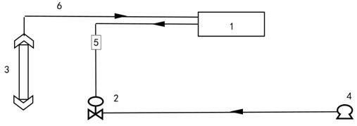
[0028] Such as figure 1 as shown, figure 1 It is a structural diagram of the water tank automatic control and vibration antifreeze device of the present invention. The water tank automatic control and vibration antifreeze device includes a PLC control system 1, an electric regulating valve 2, an electronic liquid level gauge 3, a pipeline booster pump 4, a control circuit 5, and a signal line 6.

[0029] Among them, the control circuit 5 is connected with the PLC control system 1 and the electric regulating valve 2, and is used to control the signal (4mA~20Ma or 0V~20V or depending on the electric regulating valve used) sent by the PLC control system 1 for controlling the working state of the electric regulating valve 2 2 control signal requirements)...


PUM


Abstract

The invention provides a water tank water feeding automatic control and oscillation anti-freezing device and method. The water tank water feeding automatic control and oscillation anti-freezing device comprises a PLC control system, an electric adjusting valve, an electronic liquid level meter and a control circuit, wherein the electronic liquid level meter is connected to the PLC control system and used for measuring the liquid level of a water tank and transmitting a measured liquid level signal to the PLC control system, the control circuit is connected between a PLC control signal and the electric adjusting valve and transmits a valve opening signal which is sent by the PLC control system and used for controlling a working state of the electric adjusting valve to the electric adjusting valve, and the electric adjusting valve executes the received valve opening signal and is opened by a certain valve opening. The water tank water feeding automatic control and oscillation anti-freezing device and method are suitable for automatic control of water feeding of a water tank and occasions needing anti-freezing of ground pipelines in winter, and have the advantages of being accurate in control, good in anti-freezing effect, easy to move and transport, high in automation degree, easy to operate and the like.

Description

technical field [0001] The invention relates to the technical field of oil field development, in particular to an automatic water filling control and vibration antifreezing device and method for a water tank. Background technique [0002] Thermal recovery of heavy oil is a mature oil recovery process in oilfields. Oilfield steam injection boilers are key equipment for thermal recovery of heavy oil. Steam injection boilers are often equipped with a series of auxiliary facilities to ensure continuous production of steam injection boilers. As movable steam injection boilers need to be frequently relocated to different well sites for steam injection, the water supply pipeline must be connected to the fixed water network by laying detachable pipelines from the ground. This section of the pipeline cannot be insulated with deep burial. [0003] As a storage tank for steam injection boiler water, the water tank must be kept at a reasonable level at all times to ensure continuous pr...

Claims


Application Information

Patent Timeline
Patent Type & Authority Applications(China)
IPC IPC(8): E21B43/24G05D27/02
CPCE21B43/24G05D27/02
Inventor 陈军肖刚张乃峰陈超咸朝军武八锁刘建赵磊刘冲赵汝燕王洪术
Owner CHINA PETROLEUM & CHEM CORP
Learn More