

Chassis dynamometer rotating hub tension and compression sensor mounting structure and mounting method thereof
A technology of tension and compression sensors and chassis dynamometers, which is applied in the field of dynamometers, can solve the problems of occupying a very large underground space, increasing the axial size, and large axial size, and achieve simple and high testing, reducing space occupation, and speed easy to control effects
- Summary
- Abstract
- Description
- Claims
- Application Information
AI Technical Summary
Problems solved by technology
Method used
Image

Examples
Embodiment 1
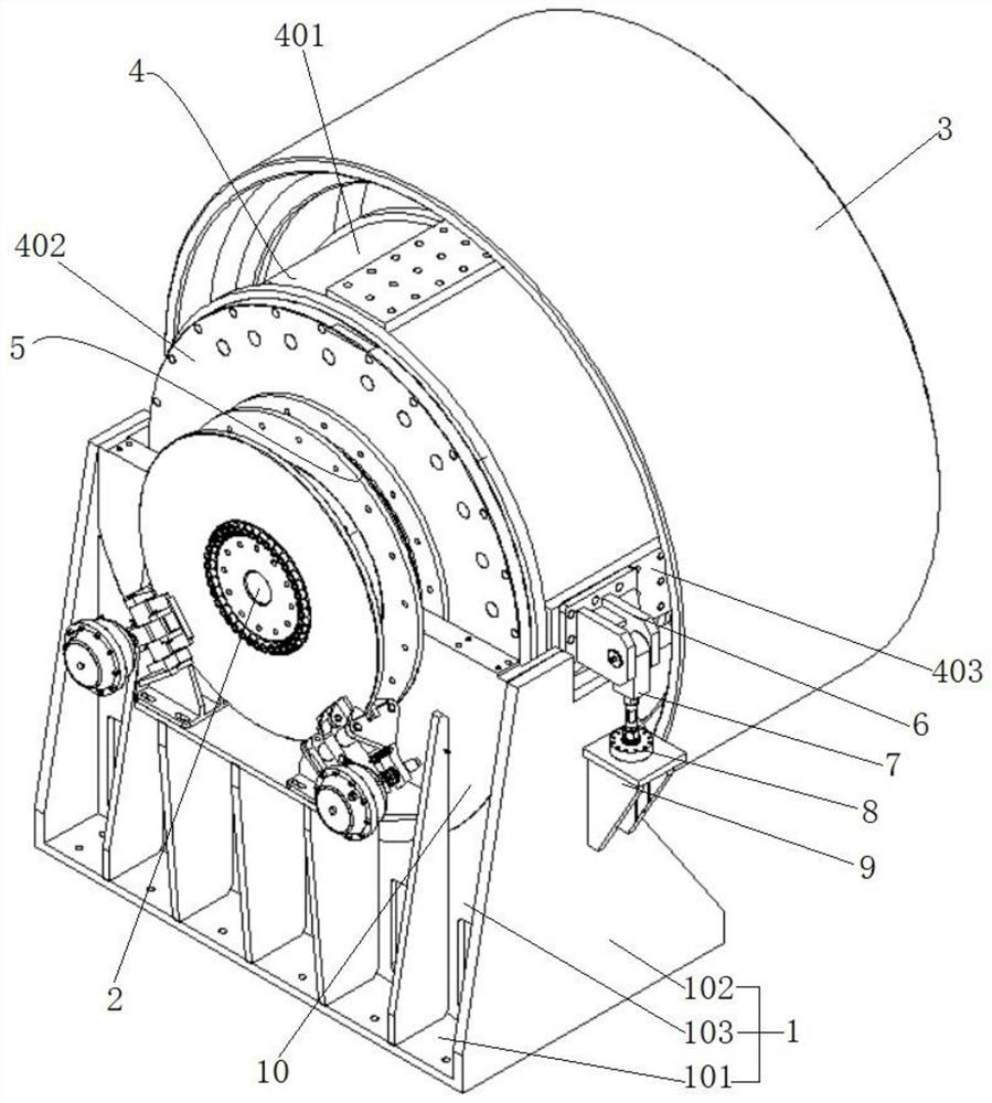
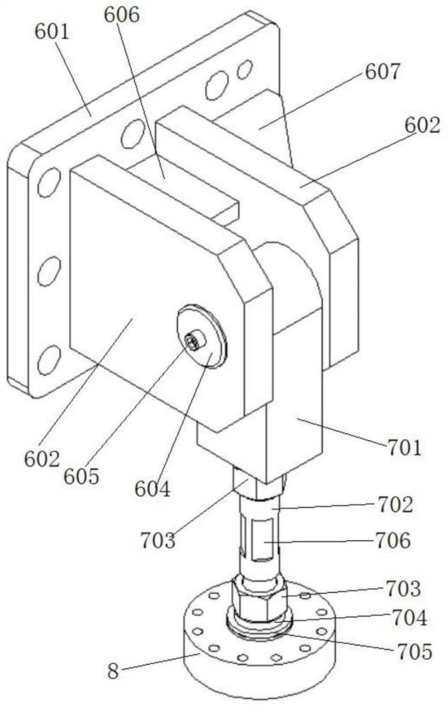
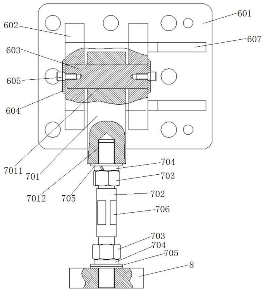
[0037] Such as figure 1 As shown, a chassis dynamometer hub tension and pressure sensor installation structure, including a support frame 1, the support frame 1 is provided with a transmission shaft 2, one end of the transmission shaft 2 protrudes from the support frame 1 and is connected to There is a rotating hub 3; the drive shaft 2 is sleeved with a drive assembly at the position above the support frame 1, and the casing 4 of the drive assembly is connected to the drive shaft 2 through a first transmission bearing. A bearing assembly 5 is connected between the casing 4 and the support frame 1; several mounting plates 403 are axially provided on the outer circumference of the casing 4, and a pull seat 6 is installed on one of the mounting plates 403; The pull base 6 is movably connected with a pull rod assembly 7, and the other end of the pull rod assembly 7 is connected with a tension and pressure sensor 8, and the tension and pressure sensor 8 is arranged on a mounting fr...
Embodiment 2
[0054] This embodiment provides an installation method for the installation structure of the tension and pressure sensor of the chassis dynamometer hub, the installation method includes installing a drive assembly on the transmission shaft 2 connected to the rotation hub 3, the transmission shaft 2 and the The drive assembly is installed on the mounting base 10 through the bearing assembly 5, and the mounting base 10 is arranged on the support frame 1; the tension and pressure sensor 8 is installed on the outer wall of the support frame 1 through the mounting frame 9 and makes the tension and pressure The central axis of the sensor 8 is perpendicular to the central axis of the transmission shaft 2, and the tension and pressure sensor 8 is vertically connected with a pull rod assembly 7, and the pull rod assembly 7 is connected and fixed to the machine of the drive assembly through the pull seat 6. shell4.
[0055] This installation method is simple and effective, and can maint...
Embodiment 3
[0057] This embodiment provides a usage state of the chassis dynamometer in the first embodiment.
[0058] Such as Figure 9 As shown, two sets of four rotating hubs 3 are arranged in parallel in the dynamometer platform. The dynamometer platform is arranged in the pit, the upper surface is flush with the ground, and only a part of the arc of the rotating hub 3 is exposed on the ground. Above, for the vehicle to drive to the hub 3 for dynamometer test; the tension and pressure sensors are all located in the underground part. During the test, it is not necessary for personnel to frequently go down the pit, and the tension and pressure sensors can be obtained directly through the host computer. The detection data obtained by the sensor.
[0059] Usually the arrangement of the hub, transmission shaft and motor of the chassis dynamometer will take up a lot of space, but the chassis dynamometer in this application adopts a compact design to minimize the axial and circumferential d...
PUM
| Property | Measurement | Unit |
|---|---|---|
| size | aaaaa | aaaaa |
| length | aaaaa | aaaaa |
Abstract
Description
Claims
Application Information