Area array industrial CT scattering correction method

A technique for scatter correction and beam hardening correction, which is used in material analysis, instruments, and measurement devices using wave/particle radiation. The effect of simplicity and few algorithm steps

Active Publication Date: 2021-07-16
CHINA WEAPON SCI ACADEMY NINGBO BRANCH
View PDF6 Cites 0 Cited by
  • Summary
  • Abstract
  • Description
  • Claims
  • Application Information

AI Technical Summary

Problems solved by technology

In area array industrial CT, due to the use of area array detectors, some effective scattering correction methods in two-dimensional CT, such as post-collimation methods, cannot be used
Therefore, the software correction method has always been used for scattering correction, but the software correction method has complex algorithms, large amount of calculation, and low efficiency.

Method used


Image

  • Area array industrial CT scattering correction method
  • Area array industrial CT scattering correction method
  • Area array industrial CT scattering correction method

Examples


Embodiment 1

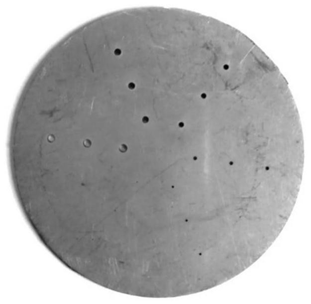
[0054] An area array industrial CT scattering correction method, comprising the following steps:

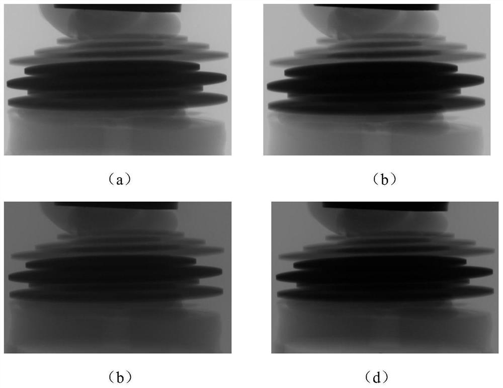
[0055] Step 1. Use an X-ray machine to perform circumferential DR scanning on the tested sample, obtain a first circumferential DR image of the tested sample, and perform beam hardening correction on the first circumferential DR image of the tested sample , to obtain I first images; wherein, the pixel of (x, y) in the i-th first image is denoted as A i (x, y), i=1, 2...I;

[0056] In this embodiment, the beam hardening correction method used in step 1 and step 2 is a stepped test block or a Monte Carlo statistical simulation method, and these beam hardening correction methods are existing methods; of course, other existing methods can also be used beam hardening correction method;

[0057] Step 2. Place an attenuation plate with a thickness of S in front of the beam output window of the X-ray machine. The material used for the attenuation plate corresponds to an attenuation coe...

Embodiment 2

[0105] Different from Embodiment 1, the beam hardening correction method used in Embodiment 2 includes the following steps:

[0106] Step a, processing N filters with different penetration thicknesses; wherein, the penetration thickness of each filter is less than or equal to the maximum penetration thickness of the tested sample; N is a positive integer;

[0107] Step b, place each filter in stages before the beam output window of the X-ray machine, and use the same scanning process to perform DR scanning on each filter to obtain the DR image of each filter; the DR image of each filter The dimensions are all c×d; wherein, the scanning process in this embodiment includes at least the parameters of tube voltage, tube current, magnification ratio, focus size and integration time; these parameters are all process parameters used when the X-ray machine performs DR scanning;

[0108] Step c, perform exponential fitting according to the gray value of the DR image of the filter in st...


PUM

PropertyMeasurementUnit
diameteraaaaaaaaaa

Abstract

The invention relates to an area array industrial CT scatter correction method, which comprises the following steps of: 1, performing circumferential DR scanning on a detected sample by using an X-ray machine to obtain I first circumferential DR images, and performing beam hardening correction on the I first circumferential DR images to obtain I first images; 2, placing an attenuation plate in front of a beam outlet window of the X-ray machine; performing circumferential DR scanning on the detected sample by adopting a scanning process which is the same as that in the step 1 to obtain I second circumferential DR images, and performing beam hardening correction on the I second circumferential DR images to obtain I second images; 3, performing scattering correction on the first image and the second image with the same scanning angle to obtain DR data after scattering correction; and 4, performing cone beam CT reconstruction by adopting the DR data after scattering correction to obtain a CT image after scattering correction. The method is simple and convenient to operate, low in attenuation plate processing requirement, few in algorithm steps and easy to implement, and scattering artifacts of images after subsequent industrial CT reconstruction are greatly reduced.

Description

technical field [0001] The invention relates to the field of CT image correction, in particular to an area array industrial CT scattering correction method. Background technique [0002] Industrial CT detection technology is a practical non-destructive detection method developed on the basis of X-ray detection technology. It has the advantages of intuitive imaging, quantitative, positioning, and qualitative accuracy. It is widely used in industrial non-destructive testing, medical and health and other fields. Scattering is common in industrial CT. When X-rays pass through an object, the Compton effect causes photons to deviate from the original direction of motion. Scattering photons not only reduces the signal-to-noise ratio of the detector, but also brings a lot of artifacts to the image. In order to suppress scattered photons, industrial CT machines usually add a collimator before the detector. With the development of X-ray tomography towards fast imaging and high-energy...

Claims


Application Information

Patent Timeline
Patent Type & Authority Applications(China)
IPC IPC(8): G01N23/046
CPCG01N23/046
Inventor 齐子诚倪培君赵洁蒋锐朱宇瑾唐盛明李红伟付康郭智敏左欣郑颖陆英豪张维国乔日东
Owner CHINA WEAPON SCI ACADEMY NINGBO BRANCH
Why Eureka
Try Eureka