
Method for forming ion implantation region

A technology of ion implantation area and implantation area, which is applied in the manufacture of electrical components, electrical solid devices, semiconductor/solid device, etc., can solve the problems of difficult control of width, reduce IMP implantation energy, etc., and achieve the effect of preventing the change of junction depth morphology

Pending Publication Date: 2021-07-16
SHANGHAI HUALI INTEGRATED CIRCUTE MFG CO LTD
View PDF9 Cites 1 Cited by
  • Summary
  • Abstract
  • Description
  • Claims
  • Application Information

AI Technical Summary

Problems solved by technology

[0003] For example, in NAND flash memory (flash), the periphery of the storage array also includes input and output devices. Compared with the storage cells in the storage array, the input and output devices are high-voltage (HV) devices, usually high-voltage N-type devices, namely HVN devices; HVN devices The ion implantation of the N-type source and drain (IOSDN) needs to be used Therefore, high implantation energy is required, and high implantation energy will lead to a deeper junction (junction) morphology in the ion implantation area. At the same time, high-energy IMP operation will make the width of the ion implantation area difficult to control, and finally make the ion implantation area CD stays about 50%
[0004] In order to improve the performance of the HVN device of NAND flash, it is necessary to reduce the IMP injection energy and reduce the thickness of the BARC layer to Dry etching is used to thin the BARC layer. The thinning is to open the BARC layer in the formation area of ​​the ion implantation area and perform dry etching thinning. The thinning of the BARC layer itself will open The opening of the area is enlarged, so there is still the problem of about 50% of the CD support in the ion implantation area

Method used


Image

  • Method for forming ion implantation region
  • Method for forming ion implantation region
  • Method for forming ion implantation region

Examples


Embodiment Construction

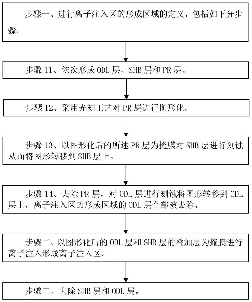
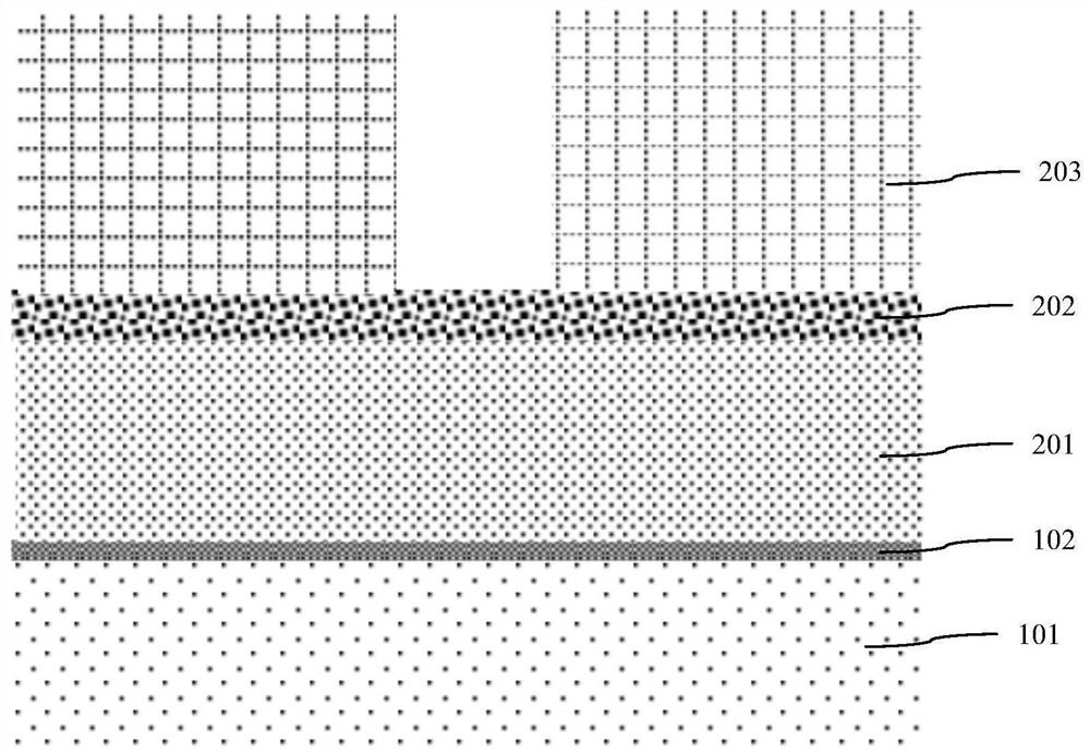
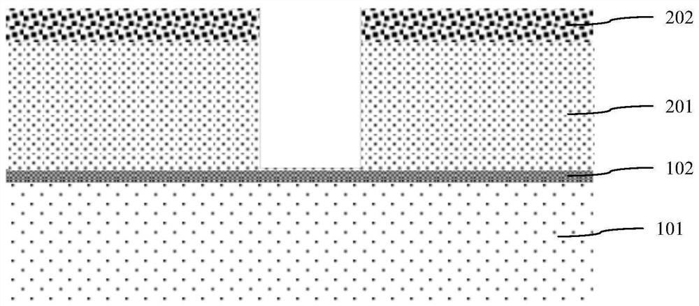
[0039] Such as figure 1 As shown, it is a flow chart of the method for forming the ion implantation region 103 according to the embodiment of the present invention; Figure 2A to Figure 2F As shown, it is a schematic diagram of the device structure in each step of the method of the embodiment of the present invention. The method for forming the ion implantation region 103 of the embodiment of the present invention includes steps:

[0040] Step 1, define the formation area of ​​the ion implantation region 103, including the following sub-steps:

[0041] Step 11, such as Figure 2A As shown, an ODL layer 201 , a SHB layer 202 and a PR layer 203 are sequentially formed on the surface of the underlying structure where the ion implantation region 103 needs to be formed.

[0042] In the embodiment of the present invention, the ODL layer 201 adopts the first carbon coating.

[0043] The SHB layer 202 uses silicon bottom anti-reflection coating.

[0044] The ODL layer 201 , the SH...


PUM


Abstract

The invention discloses a method for forming an ion implantation region. The method comprises the following steps: step 1, defining a forming region of the ion implantation region: step 11, sequentially forming an ODL layer, an SHB layer and a PR layer; step 12, patterning the PR layer by adopting a photoetching process; step 13, etching the SHB layer by taking the patterned PR layer as a mask so as to transfer the pattern to the SHB layer; step 14, removing the PR layer, etching the ODL layer by taking the SHB layer as a mask so as to transfer a pattern onto the ODL layer, and completely removing the ODL layer in the formation region of the ion implantation region; step 2, performing ion implantation by taking a superimposed layer of the patterned ODL layer and the SHB layer as a mask to form the ion implantation region; and step 3, removing the SHB layer and the ODL layer. According to the invention, the CD and junction depth of the ion implantation region can be accurately controlled.

Description

technical field [0001] The invention relates to a method for manufacturing a semiconductor integrated circuit, in particular to a method for forming an ion implantation (IMP) region. Background technique [0002] The ion implantation region is formed in the doped region on the semiconductor substrate through an ion implantation process. As the process node shrinks, the control requirements for the critical dimension (CD) and junction morphology of the ion implantation region are getting higher and higher. In the existing method, the ion implantation area is formed by sequentially forming a bottom anti-reflection coating (Bottom Anti Reflection Coating, BARC) and a photoresist. After the photoresist opens the ion implantation area, ion implantation is performed through the BARC layer to form the ion implantation area. injection area. In some ion implantation processes, in order to reduce the ion implantation energy, it is also necessary to thin the BARC layer in the ion impl...

Claims


Application Information

Patent Timeline
Patent Type & Authority Applications(China)
IPC IPC(8): H01L21/265H01L21/266H01L27/11524H01L27/11529H01L27/1157H01L27/11573H10B41/35H10B41/41H10B43/35H10B43/40
CPCH01L21/26506H01L21/266H10B41/41H10B41/35H10B43/35H10B43/40
Inventor 陶骞乔夫龙
Owner SHANGHAI HUALI INTEGRATED CIRCUTE MFG CO LTD
Learn More