
Micro-LED chip structure and preparation method

A chip structure and chip technology, applied in the direction of electrical components, electrical solid devices, circuits, etc., can solve the problems of low yield rate and difficult mass transfer technology, and achieve the effect of low cost and simple process

Pending Publication Date: 2021-07-16
SOUTHEAST UNIV
View PDF0 Cites 1 Cited by
  • Summary
  • Abstract
  • Description
  • Claims
  • Application Information

AI Technical Summary

Problems solved by technology

[0004] One way is to use mass transfer technology, which prepares the Micro-LED light-emitting dot matrix and the driving circuit separately. After completion, the Micro-LED light-emitting dot matrix is ​​removed from the sapphire or other substrate, and then placed on the driver circuit. Connections on the circuit backplane, mass transfer technology is difficult, and the yield rate is low

Method used


Image

  • Micro-LED chip structure and preparation method
  • Micro-LED chip structure and preparation method
  • Micro-LED chip structure and preparation method

Examples


Embodiment Construction

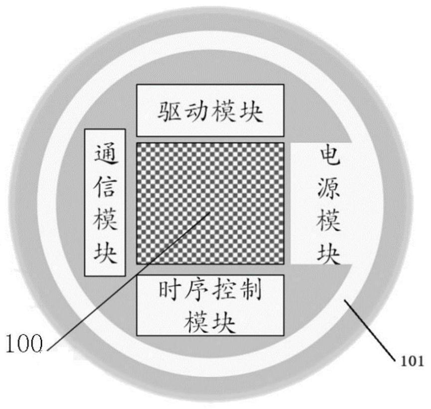
[0027] A Micro-LED chip structure of the present invention, such as figure 1 As shown, the shape of the Micro-LED chip of the present invention includes but is not limited to a circle, including a Miro-LED light-emitting dot matrix 100, a driving module, a power module, a communication module and a timing control module.

[0028] The driving module is connected to each light-emitting point in the Micro-LED light-emitting dot matrix 100 through a signal line, and is used to provide driving signals to the Micro-LED light-emitting dot matrix 100 through various signal sources such as voltage and current. The driving module includes a source driver circuit, gate drive circuit, and external compensation circuit, etc.

[0029] The timing control module is connected with the driving module for providing clock signals and coordinating the timing coordination of each circuit in the driving module.

[0030] The communication module is connected with the drive module, and is used to tra...


PUM


Abstract

The invention relates to the technical field of LED manufacturing, in particular to a Micro-LED chip structure and a preparation method. The Micro-LED chip structure comprises a Micro-LED light-emitting dot matrix, a driving module, a power supply module, a communication module and a time sequence control module, wherein the Micro-LED light-emitting dot matrix, the driving module, the power supply module, the communication module and the time sequence control module are all located on the same substrate. According to the Micro-LED chip structure, the preparation of the Micro-Led chip is completed under the condition of avoiding transfer and bonding, the process is simple, and the cost is low.

Description

technical field [0001] The invention relates to the technical field of LED manufacturing, in particular to a Micro-LED chip structure and a preparation method. Background technique [0002] Compared with the existing light-emitting devices or display and light-emitting technologies, Micro-LED has absolutely superior performance. It can avoid the material degradation and burn-in problems of OLED light-emitting devices, and has ultra-high luminous efficiency. The brightness of conventional OLED displays does not exceed 2000nits , Micro-LED display brightness can reach about 10 7 nits. Based on the above characteristics, Micro-LED can be used in the next generation of current-mode display light-emitting elements, or in optical communication. [0003] Utilizing the extremely small size and high luminous efficiency of Micro-LEDs, it is possible to make a luminous dot matrix with a resolution of more than 5000ppi. At this time, the number of light-emitting lattices on the chip ...

Claims


Application Information

Patent Timeline
IPC IPC(8): H01L27/15H01L33/00H01L33/38H01L33/62
CPCH01L33/62H01L27/156H01L33/007H01L33/38
Inventor 吴俊王鸣昕
Owner SOUTHEAST UNIV
Learn More