X-band energy selection surface

An energy selection, X-band technology, applied in the direction of reducing energy consumption, advanced technology, electrical components, etc., can solve the problems of complex time-frequency response design, and achieve the effect of improving reliability and reducing costs

Active Publication Date: 2021-07-16
NAT UNIV OF DEFENSE TECH
View PDF6 Cites 3 Cited by
  • Summary
  • Abstract
  • Description
  • Claims
  • Application Information

AI Technical Summary

Problems solved by technology

Compared with the low-frequency band, the X-band energy selection surface has higher requirements on the relevant parameters of semiconductor devices, and the time-frequency response design is more complicated, requiring more novel design ideas

Method used


Image

  • X-band energy selection surface
  • X-band energy selection surface
  • X-band energy selection surface

Examples


Embodiment Construction

[0026] The present invention will be further described below in conjunction with the accompanying drawings and specific embodiments.

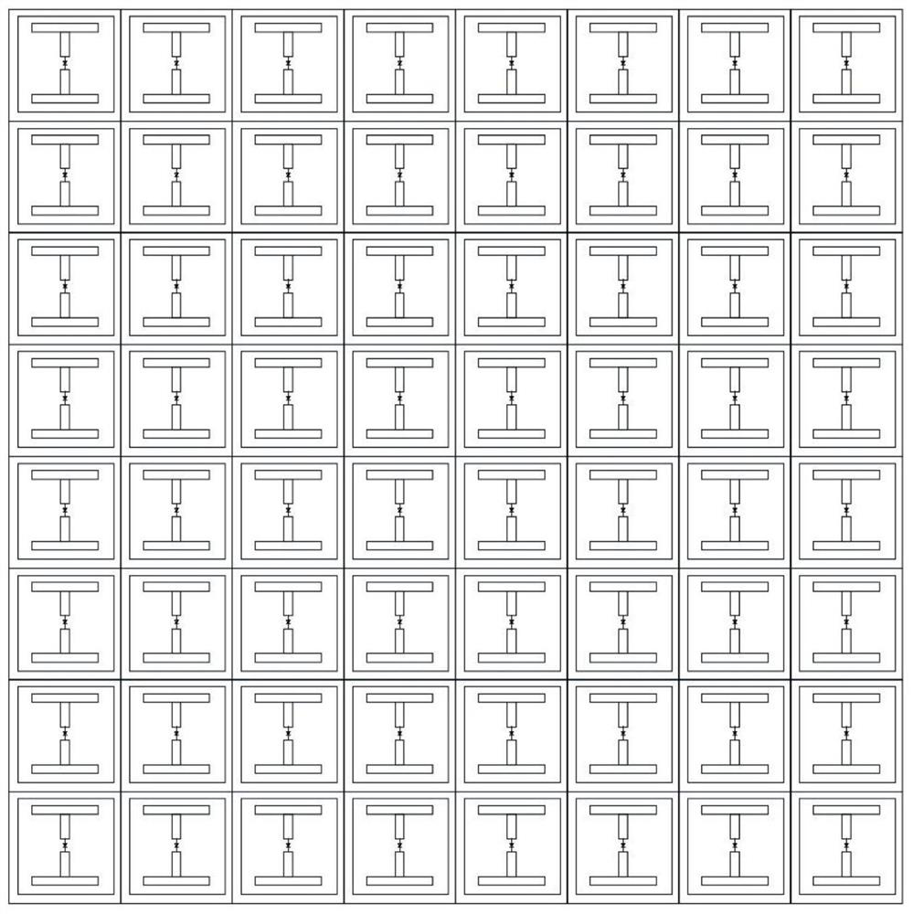
[0027] Such as figure 1 As shown, in an embodiment of the present invention, an X-band energy selective surface is provided, which includes a dielectric substrate, and a periodically arranged surface structure is printed on the upper surface of the dielectric substrate, and the surface structure includes a series of Metal square ring units distributed in an array.

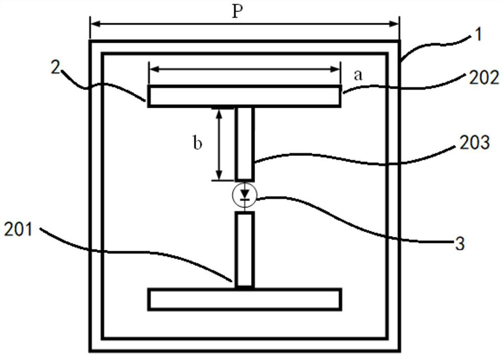
[0028] Such as figure 2 As shown, the metal square ring unit includes a square metal outer ring 1, and an I-shaped metal strip group 2 is arranged in the square metal outer ring 1; the I-shaped metal strip group 2 includes two T-shaped metal sheets 201, T-shaped The metal sheet 201 is composed of a horizontal metal sheet 202 and a vertical metal sheet 203 connected in the middle of the horizontal metal sheet 202. The vertical metal sheets 203 of the two T-shaped metal sheets are ...


PUM


Abstract

In order to prevent an electronic system from being threatened by strong electromagnetic pulses, an X-band energy selection surface is provided by the invention. The X-band energy selection surface comprises a dielectric substrate, wherein a surface structure arranged periodically is printed on the upper surface of the dielectric substrate, the surface structure comprises a series of metal square ring units distributed in an array mode, each metal square ring unit comprises a square metal outer ring, and an I-shaped metal strip group is arranged in each square metal outer ring; and each I-shaped metal strip group comprises two T-shaped metal sheets, each T-shaped metal sheet is composed of a transverse metal sheet and a longitudinal metal sheet connected between the transverse metal sheets, the longitudinal metal sheets of the two T-shaped metal sheets are oppositely arranged and are spaced by a certain distance, and a PIN diode is loaded between the longitudinal metal sheets. According to the X-band energy selection surface, X-band energy selection protection characteristics are realized for the first time, and key indexes such as insertion loss, protection effect and processing complexity are equivalent to those of a disclosed low-band energy selection surface.

Description

technical field [0001] The invention is an energy selective surface working in the X wave band, which is applied to the self-adaptive strong electromagnetic protection of the "front door" of the electronic information system. Background technique [0002] With the rapid development of electronic information technology, the degree of integration, intelligence and miniaturization of various electronic information equipment is continuously improved, its frequency is increasing day by day, energy consumption is also decreasing day by day, and its performance has been greatly improved. The sensitivity and vulnerability of electronic information equipment to strong electromagnetic interference and strong electromagnetic attack. At the same time, in addition to the strong electromagnetic interference that exists in nature, man-made strong electromagnetic interference and attack methods are becoming more and more mature. Sensitive equipment in the military and civil fields are facin...

Claims


Application Information

Patent Timeline
IPC IPC(8): H01Q15/00
CPCH01Q15/0013Y02D30/70
Inventor 虎宁查淞刘晨曦田涛康福乐黄琪瑞
Owner NAT UNIV OF DEFENSE TECH
Why Eureka
Try Eureka