Locking and unlocking device for side mold frame of bottle blowing machine

A locking device and bottle blowing machine technology, applied in the field of bottle blowing machinery, can solve the problems of easy tripping of the movable claw, consumption of high pressure gas, easy generation of impact and noise, etc. Effect

Active Publication Date: 2021-07-20
魏晋徽
View PDF4 Cites 0 Cited by
  • Summary
  • Abstract
  • Description
  • Claims
  • Application Information

AI Technical Summary

Problems solved by technology

Existing embodiments of this technical solution adopt a structure in which the fixed claw buckle faces outward and the movable claw buckle faces inward, which has the following defects: (1) The centrifugal inertial force of the movable claw faces the direction of the two claws to release. In the process, the two claws can be effectively interlocked, and a large reverse holding torque must be exerted on the movable claw; (2) when the surface of the movable claw and the fixed claw are contaminated with oil, it is easy to trip, causing serious accidents; (3) the movable claw The locking process is difficult to control, and it is prone to shock and noise
But all there is an obvious defect in above-mentioned three kinds of technical schemes: there is gap between two split bottle blow molds under the locked state, in order to eliminate this gap, a split blow bottle mold must be flexibly connected with side formwork, and both The closed air chamber must be designed and manufactured. When the opening and closing mechanism is locked and the two side mold frames cannot rotate relative to each other, high-pressure gas is input into the airtight air chamber to drive the split blowing mold that is movably connected with the side mold frame. Move and compress another split blow mold to eliminate gaps
Obviously, the cost of eliminating the gap between the two split molds through the above technical solution is relatively high: (1) The manufacturing precision of the airtight air chamber is high, and a high-priced sealing ring is required to maintain the airtightness of the air chamber; (2) The introduction and discharge of high-pressure gas Need expensive high-pressure solenoid valve; (3) need to consume high-pressure gas during operation
Not only increases the manufacturing cost of the blow molding machine, but also increases the operating cost of the blow molding machine

Method used


Image

  • Locking and unlocking device for side mold frame of bottle blowing machine
  • Locking and unlocking device for side mold frame of bottle blowing machine
  • Locking and unlocking device for side mold frame of bottle blowing machine

Examples


Embodiment 1

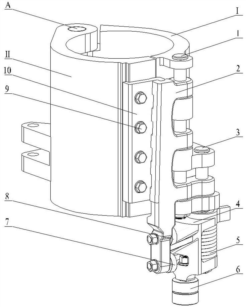
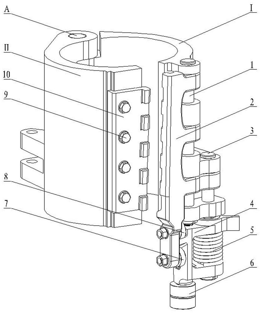
[0033] See attached figure 1 And attached figure 2 , are respectively the structural schematic diagrams of the locked state and the unlocked state of the unlocking and locking device provided in this embodiment; in the forming module for molding plastic blanks into plastic containers by a rotary blow molding machine, two subdivisions for supporting plastic containers The two side mold frames I and II of the side mold (not shown) rotate around the opening and closing rotation axis A of the side mold frames on the molding module frame (not shown). The main column 1 and the auxiliary guide pile 3 are fixedly connected with the side formwork frame I, and the axis of the guide column is parallel to the axis of the axis A. The two guide post holes on the movable buckle 2 cooperate with the main pillar 1 and the auxiliary guide pillar 3 respectively to form a moving pair, so that the movable buckle 2 can move up and down relative to the side formwork I along the guide pillar (that ...

Embodiment 2

[0047] This embodiment adopts the technical solution provided by embodiment 1, and the difference from embodiment 1 is that the load-bearing tooth surfaces of the movable buckle and the fixed buckle have the following tooth surface characteristics.

[0048] See attached Figure 8 , is a schematic diagram of tooth surface features of the movable buckle and the fixed buckle of the opening and closing device of this embodiment. The movable buckle bearing tooth surface 13 of the movable buckle is a cylindrical surface, and the straight generatrix of each tooth surface forms a fixed angle α with the moving direction B of the movable buckle (that is, the axial direction of the axis A), and each tooth surface The vertical direction is offset from each other by a distance; the fixed buckle bearing tooth surface 16 of the fixed buckle is a cylindrical surface, and the straight generatrix of each tooth surface also forms a fixed angle α with the moving direction B of the movable buckle ...

Embodiment 3

[0050] This embodiment adopts the technical solution provided by Embodiment 1, and the difference from Embodiment 1 is that the load-bearing tooth surfaces of the movable buckle and the fixed buckle have the tooth surface characteristics as described below.

[0051] See attached Figure 9 , is a schematic diagram of the tooth surface characteristics of the movable buckle and the fixed buckle of the opening and closing lock device provided in this embodiment; the tooth surfaces 13 of the movable buckle of each tooth of the movable buckle are coplanar, and the straight generatrices of the tooth surfaces are parallel to the moving direction of the movable buckle, That is, α=0°; the tooth surface 16 of the fixed buckle of each tooth of the fixed buckle is also coplanar, and the straight generatrix of the tooth surface is also parallel to the moving direction of the movable buckle, that is, α=0°. Since there is no wedge angle on the load-bearing tooth surface, this example cannot r...


PUM


Abstract

The invention relates to an unlocking and locking device for a side mold frame of a bottle blowing machine. The unlocking and locking device comprises a movable buckle movably connected with the side mold frame, a fixed buckle fixedly connected with the side mold frame and a motion conversion mechanism. The movable buckle moves up and down relative to the side mold frame in the axis direction of a side mold frame opening and closing rotating shaft. A plurality of meshing grooves are evenly distributed in the fixed buckle and the movable buckle in the axis direction of the side mold frame opening and closing rotating shaft. When teeth of the movable buckle are meshed with teeth of the fixed buckle, locking is achieved. When the teeth of the movable buckle / fixed buckle are located in the grooves of the fixed buckle / movable buckle, the movable buckle is disengaged from the fixed buckle, and unlocking is achieved. The motion conversion mechanism is composed of a swing cam and two rollers arranged on the lower portion of the movable buckle, a flange is arranged on a cylinder of the swing cam, and swing of the cam is converted into movement of the movable buckle through the contact between the two side faces of the flange of the cam and the two rollers arranged on the lower portion of the movable buckle. The device has the advantages of being simple in structure, reliable in work, convenient to manufacture and install, capable of achieving zero-clearance locking of the two split side molds of a plastic container and the like.

Description

technical field [0001] The invention relates to the technical field of bottle blowing machines, in particular to an opening and closing device for side mold frames of a rotary bottle blowing machine. Background technique [0002] The molding module used to form plastic blanks into plastic containers on the rotary blow molding machine includes: the frame and the opening and closing mold rotation axis A installed on the frame, which can be wound separately or at least one of them can be wound around the frame. The two side formworks that rotate on the axis A, the bottom formwork that can move along the axial direction of the axis A on the frame, and the two split side molds of the plastic container supported by the two side formworks and the bottom formwork Bottom molds for supported plastic containers, etc. The two side mold bases and the bottom mold base are closed, so that the two split side molds and the bottom mold of the plastic container can form a hollow cavity, and t...

Claims


Application Information

Patent Timeline
Patent Type & Authority Applications(China)
IPC IPC(8): B29C49/56
CPCB29C49/56B29C2049/566
Inventor 邹玉萍钱志良魏晋徽
Owner 魏晋徽
Why Eureka
Try Eureka