Multi-effect staged first rain storage pond

A technology of graded, regulating and accumulating tanks, applied in the field of environmental engineering, can solve the problems of increasing sewage treatment costs, low operating efficiency, waste of resources, etc., and achieve the effects of reducing sewage treatment costs, ensuring water quality requirements, and strengthening linkage.

Pending Publication Date: 2021-07-20
CCCC SECOND HARBOR ENG
View PDF0 Cites 0 Cited by
  • Summary
  • Abstract
  • Description
  • Claims
  • Application Information

AI Technical Summary

Problems solved by technology

In practical engineering applications, decentralized small-scale storage tanks have certain requirements for vacant land use, and it is difficult to build small-scale storage tanks in multiple places; centralized large-scale storage tanks have the problem of insufficient energy saving during use
At the same time, in the design process of the above-mentioned storage tank, the determination of the tank capacity is based on the maximum value determined by the local regional characteristics and rainfall type, and is designed to meet the most unfavorable conditions. Due to the uncertainty and randomness of rainfall, it is difficult to fully use Operational efficiency of storage tanks
In addition, in the actual application of the storage tank, the concentration of pollutants at different rainfall times shows certain dynamic changes, especially the concentration of pollutants in the runoff is relatively high at the beginning of the rainfall. If the rainwater with different gradient concentrations is mixed and stored in the storage tank , will inevitably increase the cost of sewage treatment
[0003] In addition, the existing storage tanks have a single function, and are generally only used for temporary storage of initial rainwater, with little other use value. Especially in sunny days, the storage tanks are basically in a state of shelving, which greatly wastes resources; Some storage tanks also have disadvantages such as low collection rate of high-concentration rainwater, extensive pollutant treatment mode, low operating efficiency, high equipment failure rate, high operation and maintenance costs, and relatively fixed location settings.

Method used


Image

  • Multi-effect staged first rain storage pond
  • Multi-effect staged first rain storage pond
  • Multi-effect staged first rain storage pond

Examples


Embodiment Construction

[0045] The present invention will be further described in detail below in conjunction with the accompanying drawings, so that those skilled in the art can implement it with reference to the description.

[0046] It should be noted that, in the description of the present invention, the terms "horizontal", "vertical", "upper", "lower", "front", "rear", "left", "right", "vertical", The orientation or positional relationship indicated by "horizontal", "top", "bottom", "inner", "outer", etc. is based on the orientation or positional relationship shown in the drawings, and is only for the convenience of describing the present invention and simplifying the description, and It is not to indicate or imply that the device or element referred to must have a particular orientation, be constructed in a particular orientation, or operate in a particular orientation, and thus should not be construed as limiting the invention.

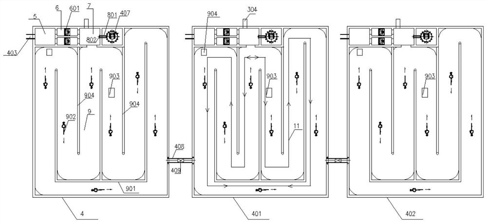
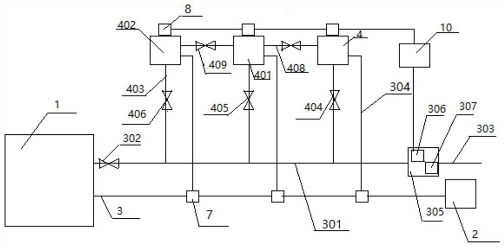
[0047] Such as figure 1 , 3 As shown, the present invention pr...


PUM


Abstract

The invention discloses a multi-effect staged first rain storage pond. The multi-effect staged first rain storage pond comprises a flow dividing device, an artificial wetland and a sewage treatment plant, wherein the flow dividing device is used for collecting first rain and dividing the first rain into a storage pond group, and the artificial wetland is used for treating the first rain; the flow dividing device comprises a rainwater pipe network group which communicates with the artificial wetland and a first sewage pipe network which communicates with the artificial wetland and the sewage treatment plant; and the storage pond group comprises a plurality of water storage pools which are arranged on the rainwater pipe network group at intervals along the water flow direction, a plurality of first rain inlet pipes which are provided with second gates and correspondingly communicate with the water storage pools and the rainwater pipe network group respectively and a plurality of second sewage pipe networks which correspondingly communicate with the water storage pools and the first sewage pipe network respectively, and an integrated pump station is arranged in any water storage pool. According to the first rain storage pond, rainwater with different concentration gradients is stored in different water storage pools, and the rainwater in the water storage pools is not interfered with one another, so that the water quality of an integrally collected water body cannot be influenced by the water quality deterioration, and the sewage treatment cost is greatly reduced.

Description

technical field [0001] The invention relates to the technical field of environmental engineering. More specifically, the present invention relates to a multi-effect graded primary rain storage pond. Background technique [0002] The existing primary rain storage tanks are mainly divided into decentralized small storage tanks and centralized large storage tanks according to different construction scales. In practical engineering applications, decentralized small storage tanks have certain requirements for vacant land use, and it is difficult to build small storage tanks in multiple places; centralized large storage tanks have the problem of insufficient energy saving during use. At the same time, in the design process of the above-mentioned storage tank, the determination of the tank capacity is based on the maximum value determined by the local regional characteristics and rainfall type, and is designed to meet the most unfavorable conditions. Due to the uncertainty and ran...

Claims


Application Information

Patent Timeline
Patent Type & Authority Applications(China)
IPC IPC(8): E03F5/10E03B3/02E03F3/02E03F5/22B01D36/04
CPCB01D36/04E03B3/02E03F3/02E03F5/10E03F5/22Y02A20/108
Inventor 杨志伟王永锋张会军刘炎张军李帅李奔谢静王涛薛国威游永龙贺泽毅刘康覃祥东
Owner CCCC SECOND HARBOR ENG
Why Eureka
Try Eureka