Double-stage axial swirler capable of strengthening oil-gas mixing in cavity and aero-engine

A two-stage swirler and swirler technology, applied in the field of aero-engines, can solve the problems of unstable precession flow of the vortex core, reduced flame stability of the combustion chamber, unfavorable flame stability, etc. Improved outlet temperature distribution, improved blending and distribution

Active Publication Date: 2021-07-20
AECC HUNAN AVIATION POWERPLANT RES INST
View PDF5 Cites 2 Cited by
  • Summary
  • Abstract
  • Description
  • Claims
  • Application Information

AI Technical Summary

Problems solved by technology

[0006] The present invention provides a two-stage axial swirler with concave cavity enhanced oil-gas mixing, to solve the problem that the precession of vortex core (PVC) flow is unstable in the flow field of the existing two-stage axial swirl, which will cause Combustion instability and the reduction of flame stability in the combustion chamber, which is not conducive to the technical problems of flame stability

Method used


Image

  • Double-stage axial swirler capable of strengthening oil-gas mixing in cavity and aero-engine
  • Double-stage axial swirler capable of strengthening oil-gas mixing in cavity and aero-engine
  • Double-stage axial swirler capable of strengthening oil-gas mixing in cavity and aero-engine

Examples


Embodiment 2

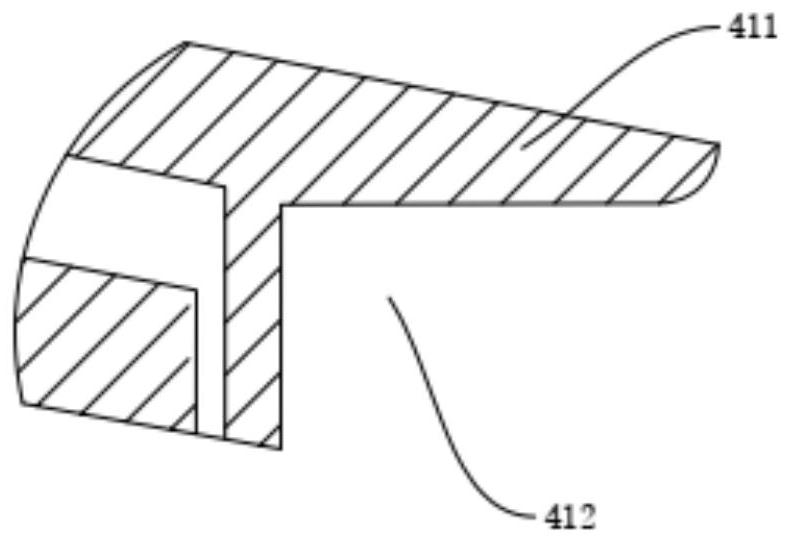
[0047] refer to image 3 The difference between this embodiment and Embodiment 1 is that the end of the guide ring 411 is vertically arranged, and the guide ring 411 is installed and used in conjunction with the flame cylinder of the aero-engine during installation, and the end of the guide ring 411 is vertically arranged, It has the effect of positioning installation.

Embodiment 3

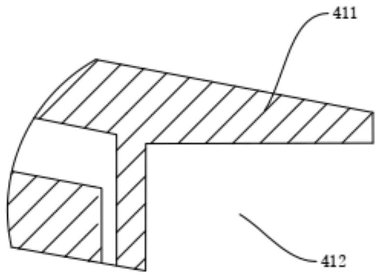
[0049] refer to Figure 4 The difference between this embodiment and Embodiment 1 is that the end of the guide ring 411 is chamfered. Processing the end of the guide ring 411 as a chamfer can reduce the adsorption of oil and gas at the end of the guide ring 411, and by The end of the ring 411 is processed into chamfers, which reduces the weight of the aero-engine while cooling the swirler shell, and by processing the ends of the guide ring 411 into chamfers, it is convenient to process the guide ring 411 Machining.

Embodiment 4

[0051] refer to Figure 5 The difference between this embodiment and Embodiment 1 is that the angle between the inner wall of the guide ring 411 and the end of the sleeve 4 is 135°, and the angle between the inner wall of the guide ring 411 and the end of the sleeve 4 is set to 135° , setting the angle between the guide ring 411 and the sleeve 4 to 135° can make the oil and gas mixed in the concave vortex 412 smoothly enter the flame tube for combustion, and pass through the gap between the guide ring 411 and the end of the sleeve 4 The inclination setting between the first can reduce the adsorption of oil and gas, the second is to increase the mixing residence time of fuel and air, and strengthen the mixing effect, and the third is to reduce the weight of the sleeve 4. The aero-engine is a precision mechanical device and is equipped with an aviation aircraft. When designing aero-engine parts, it is necessary to take into account the impact of weight, so as to reduce the weigh...


PUM


Abstract

The invention discloses a double-stage axial swirler capable of strengthening oil-gas mixing in a cavity. The double-stage axial swirler comprises a first-stage swirler and a second-stage swirler, a venturi tube is arranged between the first-stage swirler and the second-stage swirler, a sleeve is arranged on the second-stage swirler, the first-stage swirler is arranged on a center nozzle in a sleeving manner, and a flow mixing part and a cooling part are further included. The flow mixing part is arranged at the end part of the sleeve and is used for fully mixing oil and gas in a combustion chamber again; and the cooling part is arranged on the sleeve and is used for conveying cooling gas and carrying out cooling protection on a combustion chamber swirler shell, and meanwhile, the problems that combustion instability is caused, the stability of the flame of the combustion chamber is reduced and flame stability is not facilitated due to the fact that unstable vortex core precession (PVC) flow generally exists in a flow field of a double-stage axial swirler are solved.

Description

technical field [0001] The present invention relates to the technical field of aviation gas turbine engine combustors, in particular, to a two-stage axial swirler that enhances oil-gas mixing with a concave cavity, and furthermore, the present invention also relates to a cavity-enhanced oil-gas mixing Two-stage axial swirler aeroengine. Background technique [0002] The development of high-performance combustors has put forward higher requirements for fuel atomization technology, and it is necessary to achieve complete combustion in a shorter combustion zone to shorten the length and weight of the combustor; it is necessary to better organize the concentration field in the main combustion zone , in order to cope with the gas volume shortage caused by the high-temperature rising combustor used to adjust the outlet temperature field; it needs to have higher requirements for ignition performance, lean flameout range and lower pollutant emissions. [0003] It is difficult for g...

Claims


Application Information

Patent Timeline
Patent Type & Authority Applications(China)
IPC IPC(8): F23R3/38F23R3/12F23R3/28
CPCF23R3/38F23R3/12F23R3/286Y02T50/60
Inventor 王志凯江立军陈盛彭中九刘冉刘逸博
Owner AECC HUNAN AVIATION POWERPLANT RES INST
Why Eureka
Try Eureka