Eureka AIR delivers breakthrough ideas for toughest innovation challenges, trusted by R&D personnel around the world.

Fuel assembly with compact structure, reactor and mobile carrier

A technology of fuel assembly and compact structure, which is applied in related fields of reactors, can solve the problems of complex flow regulation structure, increase the amount of structural materials, unfavorable core miniaturization, etc., achieve the effect of reducing structural materials, simplifying structural design, and avoiding adverse effects

Pending Publication Date: 2021-07-20
国科中子能(青岛)研究院有限公司
View PDF0 Cites 1 Cited by
  • Summary
  • Abstract
  • Description
  • Claims
  • Application Information

AI Technical Summary

Problems solved by technology

At present, the mature design for industrial application is the fuel rod structure. The PWR fuel assembly design is conventionally adopted. It is supported by the upper and lower nozzles and the intermediate grid. Since the intermediate grid constrains the fuel rods through the cells, it needs to occupy a certain amount of space. Design space, but also requires a complex flow regulation structure, which is not conducive to miniaturization design
Some fast reactor fuel assembly designs cancel the intermediate grid support and constrain the fuel rods through the upper and lower operating heads, which is conducive to the compact design of the assembly, but the outer layer of the assembly is designed with a hexagonal cladding tube, and the cooling agent is designed for the lower operation of the assembly Runner structure, these designs increase the amount of structural materials, which is not conducive to the miniaturization of the core

Method used


Image

  • Fuel assembly with compact structure, reactor and mobile carrier
  • Fuel assembly with compact structure, reactor and mobile carrier

Examples


Embodiment 1

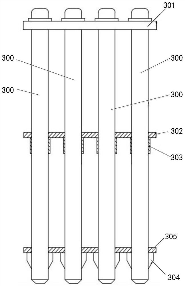
[0028] Such as figure 1 and figure 2 As shown, a fuel assembly with a compact structure in this embodiment includes a nuclear fixing plate 301, a number of fuel rods 300, a first guide plate 302, a support ring 303 and a throttle fin 304, and the throttle fin 304 is fixed on On the outer wall of one end of the fuel rods 300, several fuel rods 300 are respectively sleeved with support rings 303, and the first guide plate 302 is passed through several fuel rods 300 and supported on the support rings 303 The other end of the fuel rod 300 is assembled and fixed on the nuclear fixing plate 301; the first guide plate 302 and the support ring 303 are respectively made of core coolant, which has good safety, and the first guide plate Even if the 302 and the support ring 303 accidentally fall into the pile, they will melt by themselves before operation, and will not affect the safety of the equipment in the pile.

[0029] A fuel assembly with a compact structure in this embodiment h...

Embodiment 2

[0032] Such as figure 1 and figure 2 As shown, a fuel assembly with a compact structure in this embodiment includes a nuclear fixing plate 301, a number of fuel rods 300, a first guide plate 302, a support ring 303 and a throttle fin 304, and the throttle fin 304 is fixed on On the outer wall of one end of the fuel rods 300, several fuel rods 300 are respectively sleeved with support rings 303, and the first guide plate 302 is passed through several fuel rods 300 and supported on the support rings 303 The other end of the fuel rod 300 is assembled and fixed on the nuclear fixing plate 301; the first guide plate 302 and the support ring 303 are respectively made of core coolant, which has good safety, and the first guide plate Even if the 302 and the support ring 303 accidentally fall into the pile, they will melt by themselves before operation, and will not affect the safety of the equipment in the pile.

[0033] Such as figure 1 As shown, the fuel assembly with a compact ...

Embodiment 3

[0043] A reactor in this embodiment includes the above-mentioned compact fuel assembly. The upper ends of the fuel rods in the reactor of this embodiment are restrained and fixed by the fixing plate, the first guide plate constrains the middle part of the fuel rod, and the first guide plate located in the middle of the fuel rod is limited and supported by the support ring, and the first guide plate The core coolant and the support ring are respectively made of core coolant, which is solid at room temperature to realize the guiding function. It is melted before operation to avoid affecting the flow of core coolant, further reducing the impact on the flow of core coolant, and avoiding the impact of structural materials on neutrons. adverse effect on performance. The throttling fins can change the coolant flow area to realize core flow regulation. The invention minimizes structural materials, solves the problem of fixed support and compactness of the fuel assembly, and changes t...


PUM


Abstract

The invention relates to a fuel assembly with a compact structure, a reactor and a mobile carrier, the fuel assembly with the compact structure comprises a nuclear fixing plate, a plurality of fuel rods, a first guide plate, support rings and throttling fins, the throttling fins are fixed on the outer side walls of one ends of the fuel rods, the plurality of fuel rods are respectively sleeved with the support rings, the first guide plate is arranged on the plurality of fuel rods in a penetrating manner and is supported on the supporting ring, and the other ends of the fuel rods are assembled and fixed on the nuclear fixing plate; and the first guide plate and the support ring are respectively made of a reactor core coolant. The first guide plate restrains and limits the middle of the fuel rod, the first guide plate located in the middle of the fuel rod is limited and supported through the supporting ring, and the first guide plate and the supporting ring are made of a reactor core coolant, are in a solid state at normal temperature to achieve a guide function and are melted before operation to avoid influence on flowing of the reactor core coolant; and the influence on the flow of a reactor core coolant is further reduced, and meanwhile, the adverse influence of a structural material on neutron performance is avoided.

Description

technical field [0001] The invention relates to the technical field related to reactors, in particular to a fuel assembly with a compact structure, a reactor and a mobile carrier. Background technique [0002] The fuel assembly is one of the core components of the reactor, and its structural size affects the design of the core structure, which in turn affects the volume and weight of the reactor, and plays a key role in the miniaturization and compact design of the reactor. At present, the mature design for industrial application is the fuel rod structure. The PWR fuel assembly design is conventionally adopted. It is supported by the upper and lower nozzles and the intermediate grid. Since the intermediate grid constrains the fuel rods through the cells, it needs to occupy a certain amount of space. Design space, but also requires a complex flow regulation structure, which is not conducive to miniaturization design. Some fast reactor fuel assembly designs cancel the interme...

Claims


Application Information

Patent Timeline
IPC IPC(8): G21C3/332G21C3/356
CPCG21C3/332G21C3/356Y02E30/30
Inventor 不公告发明人
Owner 国科中子能(青岛)研究院有限公司
Why Eureka
Eureka Blog
Learn More