Vapor chamber, manufacturing method thereof and electronic equipment

A technology of vapor chamber and heat source, which is applied in the structural parts of electrical equipment, electrical components, cooling/ventilation/heating transformation, etc., and can solve the problems of insufficient supply speed of liquid working medium, uneven heat dissipation of vapor chamber, and heat dissipation power Low and other problems, to achieve the effect of preventing dry burning of the hot end, convenient operation, and large capillary suction

Pending Publication Date: 2021-07-20
江西新菲新材料有限公司
View PDF0 Cites 2 Cited by
  • Summary
  • Abstract
  • Description
  • Claims
  • Application Information

AI Technical Summary

Problems solved by technology

Since the capillary channel is generally connected as a whole, that is, the entire capillary channel is directly connected from the heat source of the vapor chamber to the cooling end, so when the length of the capillary channel is longer, the transmission distance from the cooling end to the hot end is longer, so that As a result, the supply speed of the liquid working medium cannot keep up with the speed of vaporizing the liquid working medium at the heat source, so there will be a phenomenon of liquid working medium cut-off, resulting in uneven heat dissipation of the vapor chamber, low heat dissipation power or no heat dissipation function

Method used


Image

  • Vapor chamber, manufacturing method thereof and electronic equipment
  • Vapor chamber, manufacturing method thereof and electronic equipment
  • Vapor chamber, manufacturing method thereof and electronic equipment

Examples


Embodiment 1

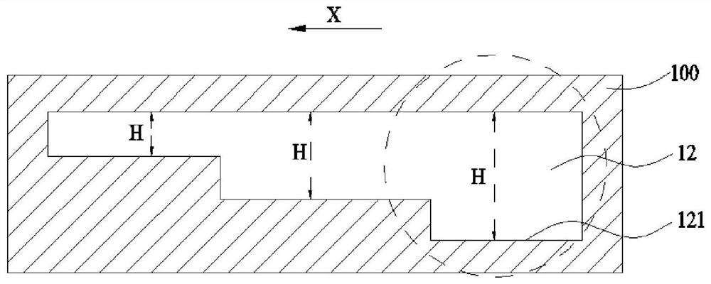
[0083] The embodiment of the present application provides a vapor chamber, which includes a housing 100. A capillary channel 12 is formed in the housing 100. The cross-sectional structure of the capillary channel 12 is as follows: image 3 as shown, image 3 Shown is a schematic diagram of the cross-sectional structure of the capillary channel 12 along its length direction, image 3 The dotted line at the middle right end shows the area close to the heat source, and the left end is the cooling end. It can be seen that the depth of the capillary channel 12 is deeper as it is closer to the heat source, and shallower as it is closer to the cooling end. image 3 In the X direction, the depth H of the capillary channel 12 gradually becomes shallower. Thus, the deeper region of the capillary channel 12 (i.e. image 3 The area at the middle right end) has a larger space and can store more liquid working fluid, while the shallower area has a smaller space and can store less liquid w...

Embodiment 2

[0091] Such as Figure 5 As shown, in the vapor chamber provided in this embodiment, the multiple capillary channels 12 are arranged in a parallel linear manner, and the multiple parallel capillary channels 12 all extend along the first direction X, and the distance between two adjacent capillary channels 12 is The space is separated by a partition rib 13, and at least one gap 131 is provided on the partition rib, and the gap 131 can communicate with two adjacent capillary channels 12. Replenishing, so that the flow of the liquid working medium is more uniform, and preventing the flow of the liquid working medium in part of the capillary channel 12 from breaking.

[0092] Due to the existence of the gap 131, a complete separating rib 13 can be separated into multiple sections separating ribs 132, such as Figure 5 As shown, the length of a section of dividing rib 132 along the first direction is b, and the width is a, and the value of a:b can be set from near the heat source ...

Embodiment 3

[0106] Such as Figure 8 , Figure 9 As shown, in the vapor chamber provided in this embodiment, the plurality of capillary channels 12' are distributed in a divergent manner, that is, the plurality of capillary channels 12' are distributed in the circumferential direction around the same center, and the plurality of capillary channels 12' extension cords pass through the center. Wherein, two adjacent capillary passages 12' are separated by radially arranged partition ribs 13', and a plurality of capillary passages 12' communicate in the circumferential direction through at least one annular passage 14, and the center of circle of the annular passage 14 is connected to the center. Coincidence, when installing, the center can be set close to the heat source. The above-mentioned annular channel 14 enables the liquid working fluid in the adjacent capillary channels 12' to replenish each other through the annular channel 14, thereby making the flow of the liquid working medium m...


PUM


Abstract

The invention discloses a vapor chamber and a manufacturing method thereof and electronic equipment, the vapor chamber comprises a shell, a capillary channel is formed in the shell, and the depth of the capillary channel is gradually reduced from the position close to a heat source to the position far away from the heat source, so that the backflow speed of a liquid working medium channel is increased, and the situation that the vapor chamber is close to the heat source and has a liquid fault is prevented; and the heat dissipation power of the vapor chamber is enhanced.

Description

technical field [0001] The present application relates to the technical field of heat dissipation, in particular to a vapor chamber, a manufacturing method thereof, and electronic equipment. Background technique [0002] As the energy consumption of electronic equipment chips is increasing, the heat generation is also increasing. Electronic equipment requires both miniaturization and sufficient heat dissipation power for heat dissipation components. Compared with other heat dissipation components, vapor chambers , can better meet the above requirements. [0003] The vapor chamber is a vacuum cavity with a capillary channel on the inner wall, and the capillary channel is used to circulate liquid working fluid. Since the capillary channel is generally connected as a whole, that is, the entire capillary channel is directly connected from the heat source of the vapor chamber to the cooling end, so when the length of the capillary channel is longer, the transmission distance fro...

Claims


Application Information

Patent Timeline
Patent Type & Authority Applications(China)
IPC IPC(8): H05K7/20
CPCH05K7/20336
Inventor 孙万华揭海欢
Owner 江西新菲新材料有限公司
Why Eureka
Try Eureka