Microwave high-pressure reaction kettle

The technology of a high-pressure reactor and a reactor, which is applied in the microwave field, can solve the problems of gas leakage of microwave equipment, rupture of separators, and temperature rise of separators, and achieves the effect of saving equipment maintenance costs, ensuring pressure stability, and ensuring compressive performance.

Pending Publication Date: 2021-07-23
NO 12 RES INST OF CETC
View PDF0 Cites 0 Cited by
  • Summary
  • Abstract
  • Description
  • Claims
  • Application Information

AI Technical Summary

Problems solved by technology

[0003] The microwave high-temperature and high-pressure reaction device not only needs to consider the microwave excitation problem, but also needs to consider the pressure bearing problem in the high-pressure environment. Most microwave energy feeding devices in the prior art use rectangular mica sheets or rectangular polytetrafluoroethylene sheets to isolate water vapor. The spacer with this shape and material has a weak pressure bearing capacity, which cannot guarantee the compressive performance of the microwave feeding part in a high-pressure environment, and it is easy to cause the breakage of the spacer, resulting in the leakage of gas inside the microwave equipment, and the diffused gas is easy to impact The microwave source (that is, the microwave generator) will cause the function of the microwave source to fail, damage the equipment, and pose a great safety risk
In addition, in the prior art, there is also a microwave energy feeding device that uses tempered glass as the material of the spacer, which can improve the pressure bearing capacity of the spacer, but there is also a large microwave loss, which causes the temperature of the spacer to rise and is easy to damage , but there are also disadvantages such as poor microwave matching performance

Method used


Image

  • Microwave high-pressure reaction kettle
  • Microwave high-pressure reaction kettle
  • Microwave high-pressure reaction kettle

Examples


Embodiment Construction

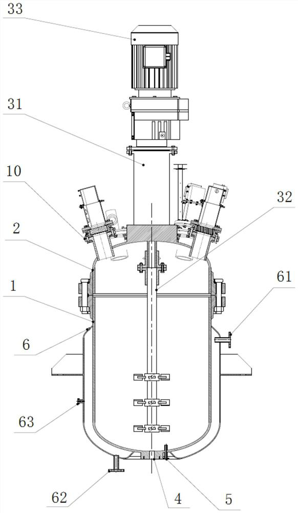
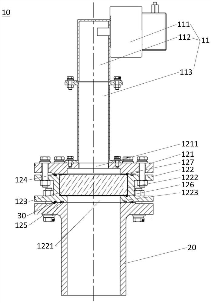
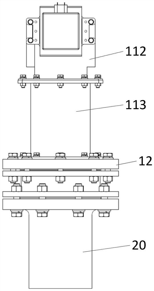
[0043] In order to illustrate the present invention more clearly, below in conjunction with preferred embodiment and accompanying drawing, the present invention is further described. Similar parts in the figures are denoted by the same reference numerals. Those skilled in the art should understand that the content specifically described below is illustrative rather than restrictive, and should not limit the protection scope of the present invention with this.

[0044] In the description of the present application, it should be noted that the orientation or positional relationship indicated by the terms "upper", "lower" and so on is based on the orientation or positional relationship shown in the drawings, and is only for the convenience of describing the present application and simplifying the description. It is not intended to indicate or imply that the device or element referred to must have a particular orientation, be constructed, or operate in a particular orientation, an...


PUM

PropertyMeasurementUnit
lengthaaaaaaaaaa
lengthaaaaaaaaaa
diameteraaaaaaaaaa

Abstract

The embodiment of the invention discloses a microwave high-pressure reaction kettle. The microwave high-pressure reaction kettle comprises a kettle body, a kettle cover, a stirring device connected to the kettle cover, and amicrowave energy feedback device fixed on the kettle cover through a connecting flange; the microwave energy feedback device comprises a microwave generator and a microwave dielectric window connected with the outlet end of the microwave generator; the microwave medium window comprises a shell with a containing cavity, the shell comprises a cover body and a medium container fixedly connected with the cover body, and the containing cavity is formed between the cover body and the medium container; the microwave dielectric window further comprises a pressure-bearing medium fixed in the containing cavity; the cover body comprises a first through hole corresponding to the outlet end of the microwave generator; the medium container comprises a second through hole corresponding to the first through hole; a top port of the connecting flange is fixedly connected with the medium container; and a bottom port of the connecting flange extends to the inner side of the kettle cover. The reaction kettle provided by the invention is higher in pressure bearing capacity and better in temperature resistance and microwave matching performance.

Description

technical field [0001] The invention relates to the field of microwave technology. More specifically, it relates to a microwave high-pressure reactor. Background technique [0002] Microwave refers to electromagnetic waves with a frequency in the range of 300MHz to 300GHz. At present, scientific research and production have higher practical requirements for microwave reaction devices, especially for traditional microwave reaction devices in terms of high power, high pressure, and high temperature. Raise new challenges. [0003] The microwave high-temperature and high-pressure reaction device not only needs to consider the microwave excitation problem, but also needs to consider the pressure bearing problem in the high-pressure environment. Most microwave energy feeding devices in the prior art use rectangular mica sheets or rectangular polytetrafluoroethylene sheets to isolate water vapor. The spacer with this shape and material has a weak pressure bearing capacity, which ...

Claims


Application Information

Patent Timeline
Patent Type & Authority Applications(China)
IPC IPC(8): B01J3/04B01J19/12
CPCB01J3/04B01J19/126
Inventor 王顺王辉杨明华甄洁毕广龙
Owner NO 12 RES INST OF CETC
Why Eureka
Try Eureka