Drilling equipment for producing washing machine inner drums
A technology for drilling equipment and washing machines, which is applied in the direction of drilling/drilling equipment, boring/drilling, metal processing equipment, etc., which can solve the problems of inconvenient use, bloated mechanism, and labor-consuming, so as to reduce production costs and mechanism The effect of streamlining and improving processing efficiency
- Summary
- Abstract
- Description
- Claims
- Application Information
AI Technical Summary
Problems solved by technology
Method used
Image
Examples
Embodiment 1
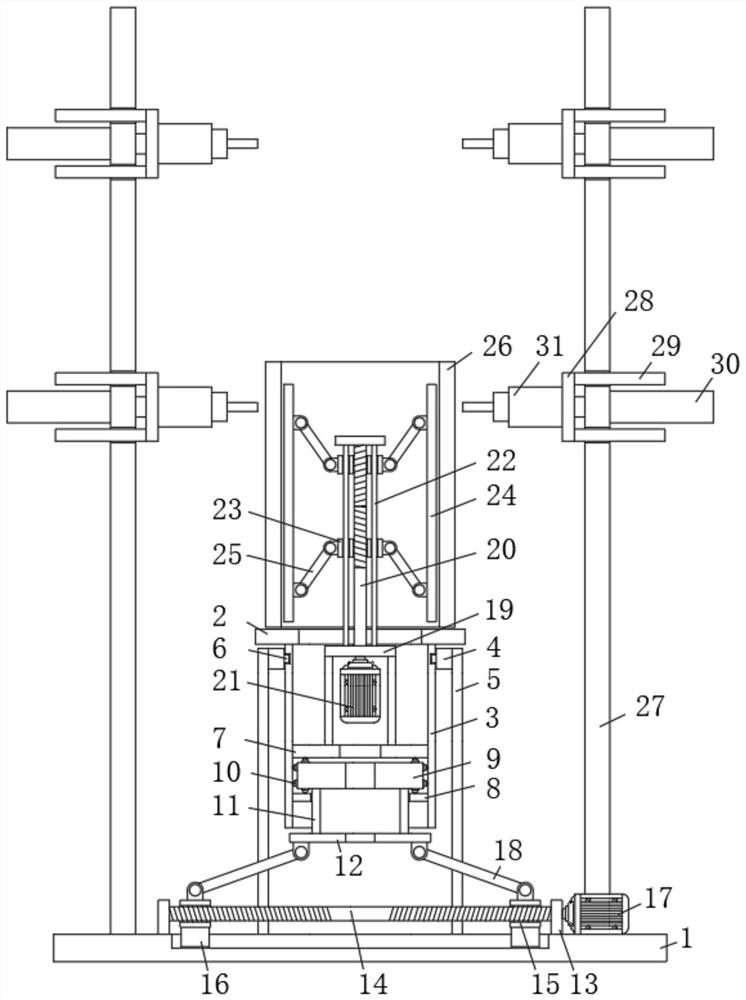
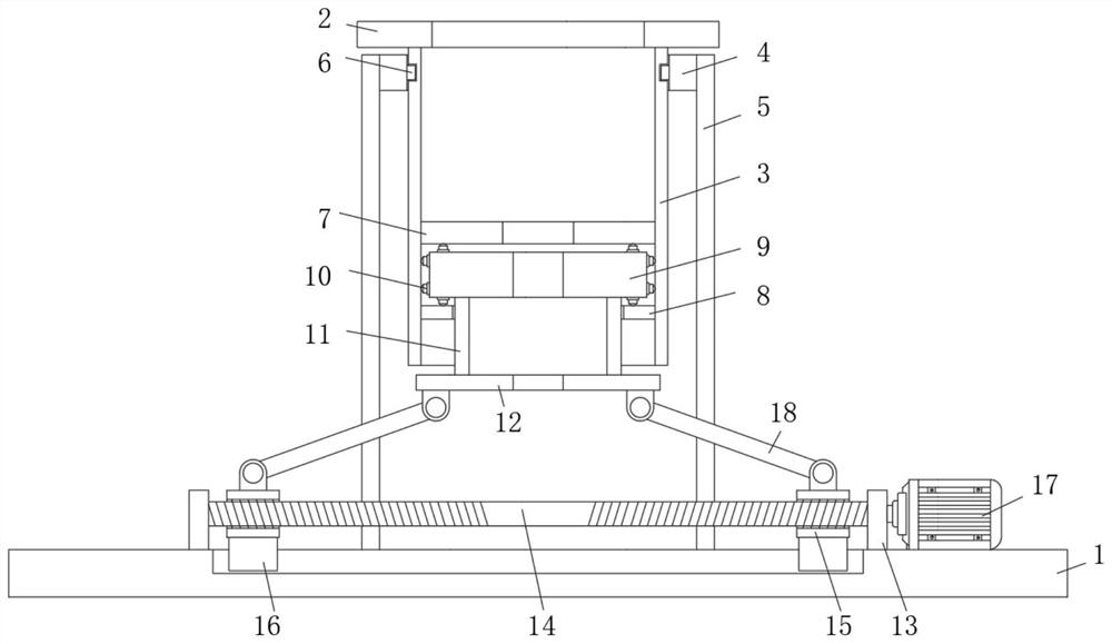
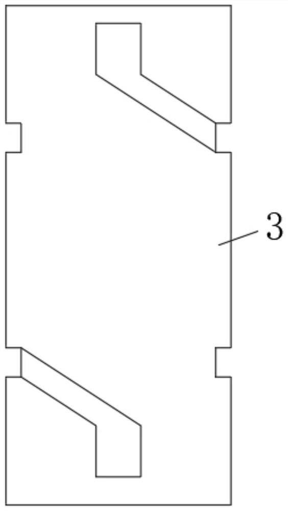
[0025] refer to Figure 1-4 , a kind of drilling equipment for the production of the inner drum of the washing machine, comprising a base plate 1, a bearing platform 2 is arranged vertically above the base plate 1, a rotating lifting mechanism is arranged between the bottom of the bearing platform 2 and the base plate 1, and the rotating lifting mechanism includes a fixed connection On the track vertical tube 3 on the bottom side of the bearing platform 2, the outer side of the track vertical tube 3 is provided with a driving guide ring 4, and a supporting column 5 is arranged between the driving guide ring 4 and the bottom plate 1, and the two sides of the track vertical tube 3 are symmetrically opened. There are track holes, and the inner walls on both sides of the driving guide ring 4 are fixedly connected with track sliders 6, one end of the track slider 6 is slidably connected in the track holes, and the inner wall of the track vertical tube 3 is fixedly connected with the...
Embodiment 2
[0028] Such as Figure 1-4 As shown, this embodiment is basically the same as Embodiment 1. Preferably, the inner tube fixing mechanism includes a mounting frame 19 fixedly erected on the top of the top limit ring 7. The top of the mounting frame 19 is rotatably equipped with a rotating shaft 20, and the mounting frame 19 The vertical rail 22 that is also fixedly installed on the top side, one side of the mounting frame 19 is fixedly installed with a servo motor 221 by bolts, one end of the rotating shaft 20 is fixed with an end of the rotating shaft 20, and the outer side of the shaft body of the rotating shaft 20 is provided with two sections in opposite directions. The threaded groove and the threaded sleeve are provided with a threaded sleeve 23, and a plurality of divergently distributed inner support plates 24 are vertically arranged in the inner cylinder 26, and the sides of each inner support plate 24 that are close to each other are respectively rotated and hinged with...
Embodiment 3
[0031] Such as Figure 1-4As shown, this embodiment is basically the same as Embodiment 1. Preferably, the punching mechanism includes several mounting frames 27 fixedly connected to the top side of the bottom plate 1, and a mounting plate 28 is provided on the side of the mounting frame 27 close to the inner cylinder 26. The frame body of the mounting frame 27 is provided with a horizontal hole, and one side of the mounting plate 28 is fixedly connected with a slide bar 29, and the body of the slide bar 29 slides through the horizontal hole, and one side of the mounting frame 27 is fixed with a cylinder 30 by bolts. , one side of the mounting plate 28 is fixed with the output rod of the cylinder 30, and the other side of the mounting plate 28 is equipped with an electric drill 31.
[0032] In this embodiment, when drilling, the cylinder 30 pushes the mounting plate 28 to move, and the cooperation of the sliding rod 29 and the horizontal hole makes the movement of the mounting...
PUM
 Abstract
Description
Claims
Application Information
 - R&D
- Intellectual Property
- Life Sciences
- Materials
- Tech Scout
- Unparalleled Data Quality
- Higher Quality Content
- 60% Fewer Hallucinations
Browse by: Latest US Patents, China's latest patents, Technical Efficacy Thesaurus, Application Domain, Technology Topic, Popular Technical Reports.
© 2025 PatSnap. All rights reserved.Legal|Privacy policy|Modern Slavery Act Transparency Statement|Sitemap|About US| Contact US: help@patsnap.com


