Double-arm collaborative robot system based on binocular vision and control method

A robot system and binocular vision technology, applied in the direction of program control manipulators, claw arms, manipulators, etc., can solve problems such as falling into local optimum, registration failure, failure to reach, etc., to improve operation accuracy, improve automation, Inexpensive effect

Active Publication Date: 2021-07-23
NANJING INST OF TECH
4 Cites 1 Cited by

AI-Extracted Technical Summary

Problems solved by technology

Traditional object recognition often uses point cloud registration methods that iterate the closest point. This method generally needs to provide a better initial value, that is, coarse registration is r...

Method used

Simultaneously adopt Levenberg-Marquardt algorithm (abbreviation LM algorithm) to solve the nonlinear optimization problem in each step, when the initial value of optimization is far away from final optimization target, use LM algorithm also can obtain a relatively good solution . The calibration method takes the minimization of the reprojection error as the optimization goal, and to a certain extent, suppresses the error effect brought about by the c...

Abstract

The invention discloses a double-arm collaborative robot system based on binocular vision. The double-arm collaborative robot system comprises a first mechanical arm device, a second mechanical arm device, a binocular detection device, a working area device, a chassis device and a control device. Point cloud data of a workpiece to be grabbed and combined by two arms cooperatively in a working area are recognized through the binocular detection device, hand-eye relationship modeling based on a binocular camera observation model is finished, and a re-projection error of pixel coordinates of the workpiece to be recognized is minimized; an optimal solution is selected from a result obtained after inverse kinematics calculation and fed back to a mechanical arm control device, the mechanical arm control device controls a first mechanical arm to move to the area where a workpiece I is located in advance, and the grabbing task is completed; then, a second mechanical arm is controlled to imitate inverse-solved closed-loop steering engine motion parameters of the first mechanical arm to move to the area where a workpiece II is located; and the two mechanical arms cooperate to complete the task. The operation precision of a robot can be effectively improved, anthropomorphic operation is achieved in a real sense, and the automation degree of industrial production is greatly improved.

Application Domain

Programme-controlled manipulatorArms

Technology Topic

Collaborative roboticsWorkspace +8

Image

  • Double-arm collaborative robot system based on binocular vision and control method
  • Double-arm collaborative robot system based on binocular vision and control method
  • Double-arm collaborative robot system based on binocular vision and control method

Examples

  • Experimental program(1)

Example Embodiment

[0064] The present invention is described in further detail now in conjunction with accompanying drawing.
[0065] It should be noted that terms such as "upper", "lower", "left", "right", "front", and "rear" quoted in the invention are only for clarity of description, not for Limiting the practicable scope of the present invention, and the change or adjustment of the relative relationship shall also be regarded as the practicable scope of the present invention without substantive changes in the technical content.
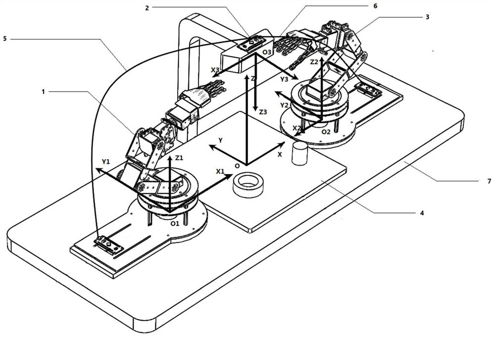
[0066] like figure 1 As shown, in one of the embodiments of the present invention, a dual-arm collaborative robot system based on binocular vision is proposed, including a left mechanical arm device 1, a right mechanical arm device 3, a binocular detection device 2, and a working area device 4. The signal line 5, the signal line 6 and the chassis device 7. The left manipulator device 1 and the right manipulator device 3 are placed at both ends of the work area device 4 and fixed on the chassis device 7. The control device first establishes the base coordinate system OXYZ, the left and right manipulator arm tool coordinate system O 1 x 1 Y 1 Z 1 , O 2 x 2 Y 2 Z 2 and measuring coordinate system O 3 x 3 Y3 Z 3. The left mechanical arm device 1 and the right mechanical arm device 3 are respectively placed at both ends of the working area, and the base coordinate system X axis and the tool coordinate system X axis 1 、X 2 Axis coincidence, Y axis and Y 1 , Y 2 Axis parallel, Z axis and Z 1 ,Z 2 axis parallel. The binocular detection device 2 includes an L-shaped connecting rod 201 and a binocular camera 202. The L-shaped connecting rod 201 is vertically fixed on the chassis device 7, and its measurement coordinate system Z 3 The axis coincides with the Z axis of the base coordinate system, and the X 3 axis coincides with the X axis, Y 3 Axis and Y, Y 1 , Y 2 parallel. The binocular detection device 2 is used to detect the workpiece I ( 402 ) and workpiece II ( 403 ) to be assembled in the working area device 4 and the end of the left mechanical arm 106 and the end of the right mechanical arm 306 .
[0067] In this embodiment, the control device includes a first manipulator rudder control board 101 for controlling the first manipulator device 1 and a second manipulator rudder control board 301 for controlling the second manipulator device 3, respectively through signal The line 5 and the signal line 6 are connected with the binocular detection device 2, the coordinates of the center point of the workpiece I (402), II (403) and the center point of the end of the mechanical arm in the measurement coordinate system output by the binocular camera 202, and the control device of the mechanical arm is responsible for In the measurement coordinate system, the end of the manipulator is controlled to approach the coordinates of any position.
[0068] like figure 2 and image 3 As shown, in one of the embodiments of the present invention, the left mechanical arm device 1 includes a chassis 111, a fixed copper column 110, a porous disk 109, a shoulder joint bus servo 108, an I-shaped connecting rod 107, and a left mechanical arm end 106 , the palm joint bus steering gear 105 , the wrist joint bus steering gear 104 , the elbow joint bus steering gear 103 , the bottom connection mechanism 102 , and the left mechanical arm chassis 111 is fixed on the chassis device 7 . The right mechanical arm device 3 includes a chassis 311, a fixed copper column 310, a porous disc 309, a shoulder joint bus steering gear 308, an I-shaped connecting rod 307, a right mechanical arm end 306, a palm joint bus steering gear 305, a wrist joint The bus steering gear 304 , the elbow joint bus steering gear 303 , the bottom connection mechanism 302 , and the right mechanical arm chassis 311 are fixed on the chassis device 7 . The binocular detection device 2 includes an L-shaped connecting rod 201 and a binocular camera 202 . The working area device 4 includes a bottom plate 401 on which the workpiece 402 and the workpiece 403 are located.
[0069] like Image 6 As shown, in one of the embodiments of the present invention, a dual-arm collaborative robot control method based on binocular vision specifically includes the following steps:
[0070] S1, establish the base coordinate system OXYZ, and the working coordinate system O of the left and right mechanical arms 1 x 1 Y 1 Z 1 , O 2 x 2 Y 2 Z 2 and measuring coordinate system O 3 x 3 Y 3 Z 3.
[0071] S2, collect the point cloud data of the workpiece I402 and the workpiece II403, and output the coordinates of the workpiece I402, the workpiece II403 and the center point of the end of the mechanical arm in the measurement coordinate system by taking the center of gravity point as the center point through the binocular camera 202.
[0072] S3, the binocular camera tracks the spatial pose of the left and right ends of the manipulator in real time, establishes a hand-eye relationship model based on the binocular camera, and minimizes the reprojection error of coordinates at any position in the measurement coordinate system to reduce the left , The error between the center point of the end of the robot arm and the center point of the workpiece to be grasped during the cooperative grasping process of the right mechanical arm, and the error between the center points of the workpiece I402 and the workpiece II403 during the cooperative combination process.
[0073] S4, the left and right robotic arms are controlled by the robotic arm control device to carry out double-arm cooperative grasping and combination of the workpiece I402 and the workpiece II403, and complete the assembly task of the workpiece I402 and the workpiece II403.
[0074] like Image 6 As shown, in one of the embodiments of the present invention, the base coordinate system OXYZ is established in the dual-arm collaborative robot device and control method based on binocular vision, and the left and right mechanical arm working coordinate systems O 1 x 1 Y 1 Z 1 , O 2 x 2 Y 2 Z 2 and measuring coordinate system O 3 x 3 Y 3 Z 3 Specifically include the following steps:
[0075] Take the center point O of the working area as the coordinate origin, and take the center point O of the chassis of the left and right robotic arms 1 , O 2 connection is the X axis, perpendicular to The direction of the connection line is the Y axis, the Z axis is established according to the right-hand rule, and the base coordinate system OXYZ is established; the center point O of the chassis of the left mechanical arm is 1 as the origin of coordinates, with direction is X 1 Axis, the direction parallel to the Y axis is Y 1 Axis, parallel to the Z axis to establish a tool coordinate system for the Z1 axis O 1 x 1 Y 1 Z 1 , take the center point O of the chassis of the right manipulator 2 as the origin of coordinates, with direction is X 2 Axis, the direction parallel to the Y axis is Y 2 axis, and the direction parallel to the Z axis is Z 2 Axis establishes tool coordinate system O 2 x 2 Y 2 Z 2; Take the binocular camera viewing angle center O of the binocular detection device 3 is the coordinate origin, and the direction parallel to the X axis is X 3 Axis, the direction parallel to the Y axis is Y 3 axis to Axis direction and coincide with Z is Z 3 The axis establishes the measurement coordinate system O 3 x 3 Y 3 Z 3.
[0076] like Image 6 As shown, in one of the embodiments of the present invention, the point cloud data of the workpiece I402 and the workpiece II403 are collected in the dual-arm collaborative robot device and control method based on binocular vision, and the center of gravity is taken as the center through the binocular camera 202 The point method, outputting the coordinates of the workpiece I402, the workpiece II403 and the center point of the end of the mechanical arm in the measurement coordinate system specifically includes the following steps:
[0077] Place a calibration board in the working area, and on the premise of ensuring that the size of the working area and the calibration board are consistent with the installation position, use Zhang Zhengyou calibration method to calibrate the internal parameters of the binocular camera, and determine the points on the working area in the base coordinate system and measurement coordinates One-to-one correspondence between departments. The obtained point cloud data of workpiece I402 and workpiece II403 in the working area, the coordinates of the center point of workpiece I402, workpiece II403 and the center point of the end of the mechanical arm in the measurement coordinate system output by the binocular camera 202, the mechanical arm control device is responsible for measuring coordinates Control the end of the robotic arm close to the center of the workpiece.
[0078] like Image 6 As shown, in one of the embodiments of the present invention, in the dual-arm collaborative robot device and control method based on binocular vision, the binocular camera tracks the spatial pose of the left and right mechanical arm ends in real time, and establishes a hand-eye view based on the binocular camera. Relational model, by minimizing the reprojection error of the coordinates at any position in the measurement coordinate system, the error between the center point of the end of the robot arm and the center point of the workpiece to be grasped is reduced during the collaborative grasping process of the left and right manipulators And the error between the center point of the workpiece I402 and the workpiece II403 in the collaborative combination process, specifically includes the following steps:
[0079] Step 1. Hand-eye relationship modeling based on binocular camera
[0080] The image collected by the binocular camera is stored in the form of an M×N matrix. The coordinates of the elements in the matrix are pixel coordinates (m, n), and the m-axis and n-axis are perpendicular to each other and parallel to the x-axis and y-axis of the base coordinate system, respectively. , the coordinates of the origin O in the m-n pixel coordinate system are (m 0 , n 0 ), the physical dimensions of each pixel in the X-axis and Y-axis directions are d x 、d y , then the relationship between the base coordinate system and the pixel coordinate system can be expressed as:
[0081]
[0082] Among them, this step is used to convert the pixel points on the image collected by the binocular camera, especially the pixel coordinates corresponding to the points on the workpiece and the end of the mechanical arm, into points on the base coordinate system (x, y, z ).
[0083] In a homogeneous coordinate system, it can be expressed as:
[0084]
[0085] Further according to the perspective projection model of the binocular camera, the following relationship can be obtained:
[0086]
[0087] The center of view of the binocular camera to the origin of the base coordinates The length of is the effective focal length f, (x 3 ,y 3 ,z 3 ) is a point on the survey coordinate system. Then the transformation relationship between the measurement coordinate system and the base coordinate system can be expressed in homogeneous coordinates as:
[0088]
[0089] Among them, this step completes the mapping of the points of the base coordinate system to the measurement coordinate system, which is also the second step in the control method of the dual-arm collaborative robot based on binocular vision: collecting the point cloud data of the workpiece I402 and the workpiece II403, The basis for outputting the coordinates of the workpiece I402, the workpiece II403 and the center point of the end of the mechanical arm in the measurement coordinate system is based on taking the center of gravity point as the center point by the binocular camera 202.
[0090] After determining the one-to-one correspondence between the base coordinate system of the point on the work area and the measurement coordinate system, we can deduce the pose of the calibration board relative to the binocular camera through the relationship between the end of the manipulator and the calibration board. The extrinsic parameters of the eye camera, where the conversion relationship of the extrinsic parameters of the hand-eye model is as follows Figure 7 shown, where O 3 , O, Q 1 , O 2 , O 1 ' and O 2 ' are the center points of the binocular camera, the working area, the end of the first manipulator, the end of the second manipulator, the chassis of the first manipulator and the end of the second manipulator, and the coordinate transformation is carried out along the direction of the solid line and the direction of the dotted line. equivalent. Therefore the following equation can be obtained:
[0091]
[0092]
[0093] Among them, formula (5.1) corresponds to the first manipulator device, formula (5.2) corresponds to the second manipulator device, and T represents the rotation-translation matrix, including two parts of rotation and translation. The rotation part contains three unknowns, that is, three rotation angles around the X, Y, and Z axes (θ x , θ y , θ z ). The rotation matrix expressed in Euler angles is:
[0094]
[0095] The translation part contains 3 unknowns (t x , t y , t z ). This step is mapped to pixel coordinates through the pose relationship between the working area and the ends of the left and right manipulators, the pose relationship between the ends of the left and right manipulators and their chassis, the hand-eye transformation relationship, and the perspective projection transformation relationship of the binocular camera. Thus, a hand-eye relationship model based on the binocular camera observation model is established:
[0096]
[0097]
[0098] Among them, formula (7.1) is the hand-eye relationship model corresponding to the first manipulator device, formula (7.2) is the hand-eye relationship model corresponding to the second manipulator device, [m n] T , [x 3 the y 3 z 3 ] T is the observed data, [m n] T Obtained by binocular cameras, The return is performed by the end of the first arm and the end of the second arm, and is the model parameter to be solved.
[0099] Step 2. Solving the hand-eye relationship based on minimizing the reprojection error
[0100] The optimization method of formulas (7.1) and (7.2) is to minimize the reprojection error. When the model parameters minimize the reprojection errors of all feature points, the optimal model parameters under the current observation are obtained.
[0101] Take n sets of observation data as input data, and set the model parameters and the model parameters between the end of the kth manipulator and the binocular of the second manipulator device Substitute the known parameters into the objective equation to be solved, and the model parameters between the k-1th manipulator base and the binocular Model parameters between the k-1th manipulator base and the binocular with the second manipulator device As an initial value for optimization, a non-linear least squares solution is used The optimized objective function is:
[0102]
[0103]
[0104] Among them, formula (8.1) is the objective function optimized by the first manipulator device, and formula (8.2) is the objective function optimized by the second manipulator device Represent point q on the pixel coordinate system and point P on the measurement coordinate system respectively. Since the mechanical structure of the left arm and the right arm are the same, the installation position is also mirrored on both sides of the working area. The final objective function can be combined into one:
[0105]
[0106] When the objective function is minimized, the final optimization result is obtained Otherwise set k=k+1. Its meaning is to select the most accurate observation data from n sets of data as the best binocular camera positioning result, that is, the coordinate value in the measurement coordinate system.
[0107] At the same time, the Levenberg-Marquardt algorithm (LM algorithm for short) is used to solve the nonlinear optimization problem in each step. When the optimized initial value is far from the final optimization goal, a relatively good solution can also be obtained by using the LM algorithm. The calibration method takes the minimization of the reprojection error as the optimization goal, and to a certain extent, suppresses the error effect brought about by the calibration data collection, and can obtain higher-precision calibration results. Adopting this method will advantageously reduce the error between the center point of the end of the mechanical arm and the center point of the workpiece to be grasped during the cooperative grasping process of the left and right mechanical arms and the error between the center point of the workpiece I402 and the workpiece II403 during the cooperative combination process .
[0108] like Image 6 As shown, in one of the embodiments of the present invention, in the dual-arm collaborative robot device and control method based on binocular vision, the left and right mechanical arms are controlled by the robotic arm control device to perform dual-arm cooperative grasping of the workpiece I402 and the workpiece II403 Combining with and completing the assembly task of workpiece I402 and workpiece II403 specifically includes:
[0109] According to the geometric parameter values ​​of the DH model of the manipulator and the expected pose of the end, use the existing technology to solve the inverse kinematics equation to obtain the value of each joint variable when the end reaches the pose. There are 8 sets of solutions in total. According to the smallest range of motion of the robot and the shortest stroke Arrived joint angles, determine a set of optimal solution joint angles. According to this optimal solution, the left mechanical arm is controlled to move to the area where the workpiece I402 is located to complete the grabbing task; then, the right mechanical arm is controlled to follow the movement track of the center point of the end of the left mechanical arm to the area where the workpiece II403 is located; finally, the left, The right robotic arm cooperates to complete the task requirement of assembly. At the same time, the binocular detection device 2 will continuously collect the pose and posture of the ends of the arms, and under the premise of minimizing the re-projection error, obtain the coordinates of the center point of the end of the manipulator and perform proximity feedback with the workpiece I402 and workpiece II403 to be grasped to ensure It can correctly grab the workpiece I402 and the workpiece II403, and complete the assembly task.
[0110] The above are only preferred implementations of the present invention, and the protection scope of the present invention is not limited to the above-mentioned embodiments, and all technical solutions under the idea of ​​the present invention belong to the protection scope of the present invention. It should be pointed out that for those skilled in the art, some improvements and modifications without departing from the principle of the present invention should be regarded as the protection scope of the present invention.

PUM

no PUM

Description & Claims & Application Information

We can also present the details of the Description, Claims and Application information to help users get a comprehensive understanding of the technical details of the patent, such as background art, summary of invention, brief description of drawings, description of embodiments, and other original content. On the other hand, users can also determine the specific scope of protection of the technology through the list of claims; as well as understand the changes in the life cycle of the technology with the presentation of the patent timeline. Login to view more.

Similar technology patents

Multi-station automobile part laser welding equipment

ActiveCN110919181AImprove working accuracy
Owner:SUZHOU LVDIAN INFORMATION TECH CO LTD

Automatic reinforcement binding robot for building construction

InactiveCN113062605AImprove working accuracyAvoid the risk of artificial binding
Owner:NORTHEASTERN UNIV

New energy automobile charger

ActiveCN105598941Ahigh degree of automationlarge bending range
Owner:夏林嘉 +1

Classification and recommendation of technical efficacy words

  • high degree of automation
  • Improve working accuracy

High-fineness urban three-dimensional modeling method

Owner:星际空间(天津)科技发展有限公司

Bolt machining all-in-one machine

Owner:ANHUI LIUFANG ZHONGLIAN MECHANICAL SHARE

Multi-station automobile part laser welding equipment

ActiveCN110919181AImprove working accuracy
Owner:SUZHOU LVDIAN INFORMATION TECH CO LTD

Automatic reinforcement binding robot for building construction

InactiveCN113062605AImprove working accuracyAvoid the risk of artificial binding
Owner:NORTHEASTERN UNIV
Why Eureka
Try Eureka