
Building wall pipeline laying grooving equipment

A slotting equipment and construction technology, applied in stone processing equipment, stone processing tools, work accessories, etc., can solve the problem of affecting the health of workers in the use environment, the slotting machine does not have a dust suction device, and affects the aesthetic effect of pipe slots, etc. problems, to achieve the effect of ensuring the use environment and physical health, improving the scope of application and flexibility, and facilitating movement

Inactive Publication Date: 2021-07-23
马鞍山市新丰建筑安装有限公司
View PDF0 Cites 0 Cited by
  • Summary
  • Abstract
  • Description
  • Claims
  • Application Information

AI Technical Summary

Problems solved by technology

[0003] At present, the existing wall pipe slotting machine has a simple structure. When slotting a straight line pipe, since there is no limit structure for protection, it is easy to produce deviation when opening, which affects the aesthetic effect of the pipe slot on the wall; Moreover, the existing slotting machine does not have any dust collection device. When in use, the dust generated is relatively large, which affects the working environment and health of the staff.

Method used


Image

  • Building wall pipeline laying grooving equipment
  • Building wall pipeline laying grooving equipment
  • Building wall pipeline laying grooving equipment

Examples


Embodiment 1

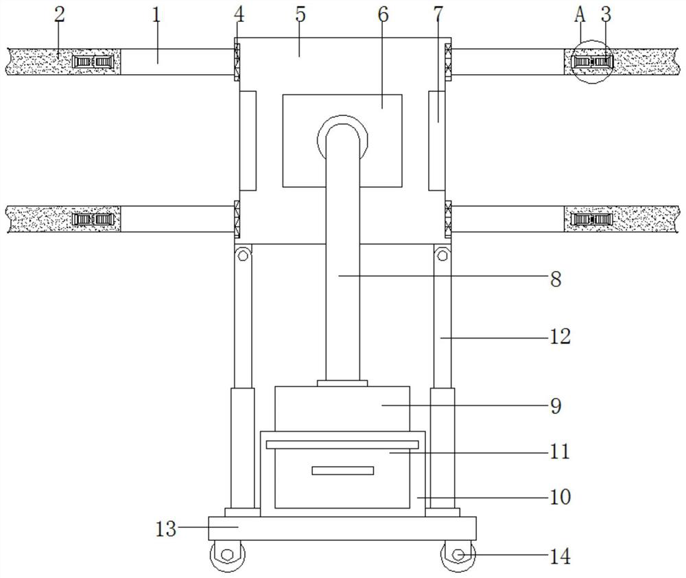
[0029] see Figure 1-2 , a wall pipe laying slotting equipment for construction, comprising a first plate body 1 and a second plate body 2, the first plate body 1 is provided with two groups, and placed in parallel, the outer wall of the first plate body 1 is slidably connected with a sliding Block 4, the outer wall of slide block 4 is fixedly connected with moving plate 5, and the middle interior of moving plate 5 is fixedly installed with slotting machine 6, and the outer wall of slotting machine 6 is fixedly installed with telescopic pipe 8, and one end of telescopic pipe 8 is fixedly installed with The vacuum cleaner 9 has a box body 10 fixedly installed under the vacuum cleaner 9 , and a material storage box 11 is clamped inside the box body 10 ; a bottom plate 13 is fixedly connected to the bottom of the box body 10 . The left and right ends above the bottom plate 13 are fixedly equipped with telescopic rods 12 , and the top of the telescopic rods 12 is flexibly connecte...

Embodiment 2

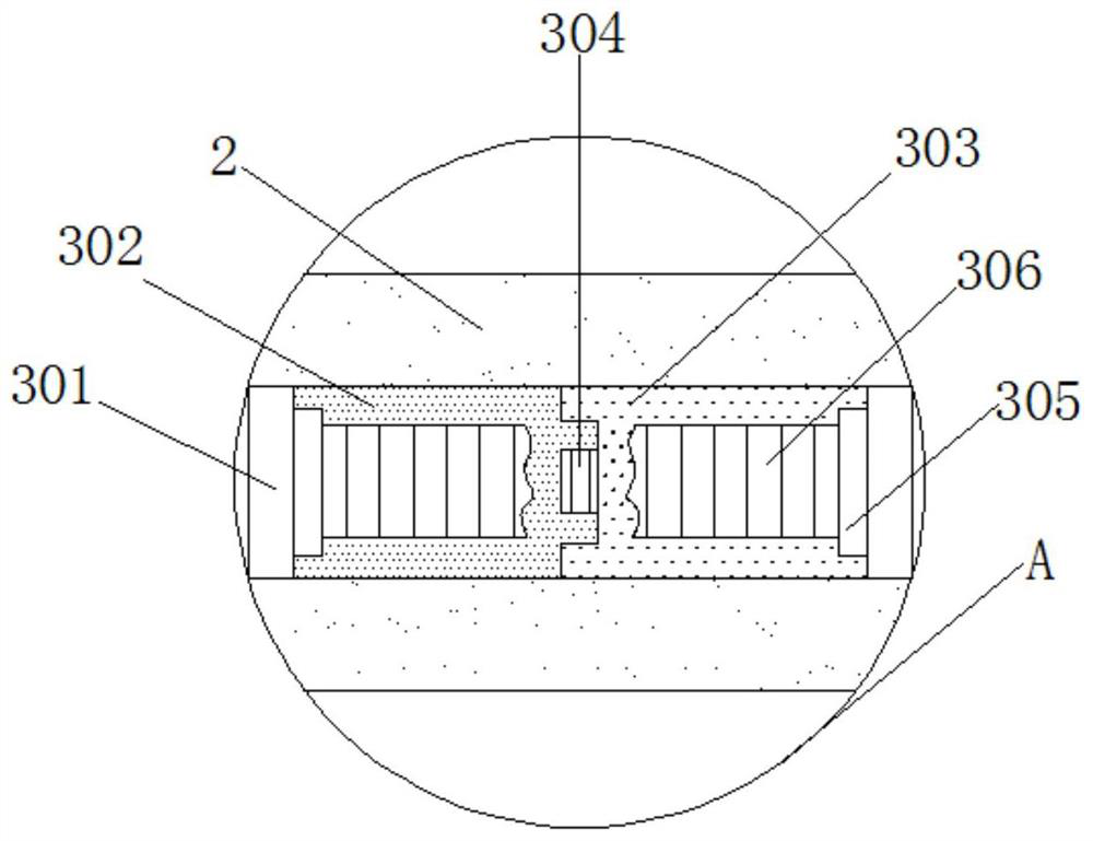
[0033] see Figure 1-5, the building uses wall pipe laying slotting equipment, the left and right sides of the first plate body 1 are clamped with the second plate body 2, and a clamping mechanism 3 is arranged between the first plate body 1 and the second plate body 2, and the clamping The connecting mechanism 3 includes a card slot 301, a first clamping plate 302, a second clamping plate 303, a rotating shaft 304, a connecting plate 305, a first spring 306, a connecting shaft 307, a guide rod 308, a sleeve 309, a second spring 310 and a limiter. Position plate 311; the inside of the second plate body 2 is provided with a card slot 301, the inside of the card slot 301 is provided with a first card plate 302 and a second card plate 303, the first card plate 302 and the second card plate 303 One end is connected by being provided with a rotating shaft 304; the other end of the first clamping plate 302 and the second clamping plate 303 are fixedly connected with a connecting pla...


PUM


Abstract

The invention discloses building wall pipeline laying grooving equipment, and relates to the field of wall pipeline grooving equipment. The building wall pipeline laying grooving equipment comprises two groups of first plate bodies and a second plate body, the first plate bodies are arranged in parallel, the outer walls of the first plate bodies are slidably connected with sliding blocks, the outer walls of the sliding blocks are fixedly connected with a moving plate, a grooving machine is fixedly installed in the middle of the movable plate, a telescopic pipeline is fixedly installed on the outer wall of the grooving machine, a dust collector is fixedly installed at one end of the telescopic pipeline, a box is fixedly installed below the dust collector, and a storage box is clamped in the box. According to the building wall pipeline laying grooving equipment, through arrangement and cooperation of the first plate bodies and a telescopic rod, the grooving machine can be linearly limited, so that the grooving machine can straightly conduct grooving, and the problem of inclination is solved.

Description

Technical field: [0001] The invention relates to the field of wall pipeline slotting equipment, in particular to a wall pipeline laying slotting equipment for construction. Background technique: [0002] The slotting machine is mainly used for asphalt, cement pavement pavement repair, drainage pipes, gas pipes, electric wire pipes and optical cable pipes. Quickly cut the pavement into uniform grooves with a rotary saw to form a new joint surface. Optimize the contact surface between the filling material and the slot, and strengthen the bonding tightness between the filling material and the side wall of the slot. [0003] At present, the existing wall pipe slotting machine has a simple structure. When slotting a straight line pipe, since there is no limit structure for protection, it is easy to produce deviation when opening, which affects the aesthetic effect of the pipe slot on the wall; Moreover, the existing slotting machine does not have any dust collection device, and...

Claims


Application Information

Patent Timeline
IPC IPC(8): B28D1/22B28D7/02B28D7/00
CPCB28D1/22B28D7/00B28D7/02
Inventor 王亮
Owner 马鞍山市新丰建筑安装有限公司
Learn More