Driving device for injection molding machine and injection molding system thereof

A driving device and injection molding machine technology, applied in the field of injection molding machines, can solve problems such as difficult ejection of injection molding products, unsuitable injection molding products, and low stroke precision, and achieve the effects of rapid change, wide application range, and high flexibility

Inactive Publication Date: 2021-07-23
柏松
View PDF1 Cites 0 Cited by
  • Summary
  • Abstract
  • Description
  • Claims
  • Application Information

AI Technical Summary

Problems solved by technology

[0004] However, there are still relatively obvious defects in its use: 1. When the above-mentioned device is in use, the ejector rod at the fixed position will be fully ejected, but in some injection molding products, when the ejector rod is driven out of the position When it overlaps with the inner hole position of the convex column of the injection molded product, the ejector pin will be inserted into the inner hole of the injection molded product. At this time, the rise of the ejector pin will not cause the demoulding effect, making it difficult for the injection molded product to be ejected from the mold. Generally, it is necessary to modify the position of the boss on the injection molded product, but changing the position of the boss may affect the strength of the entire product, causing product deformation, or it is cumbersome to perform molding operations on the inner hole of the boss at a later stage; 2. The above-mentioned device uses an oil cylinder to drive the ejector rod. Although the displacement caused by the oil cylinder drive changes quickly, the precision of the stroke is low, and it is not suitable for demoulding drive of injection molded products that require refinement.

Method used


Image

  • Driving device for injection molding machine and injection molding system thereof
  • Driving device for injection molding machine and injection molding system thereof
  • Driving device for injection molding machine and injection molding system thereof

Examples


Embodiment 1

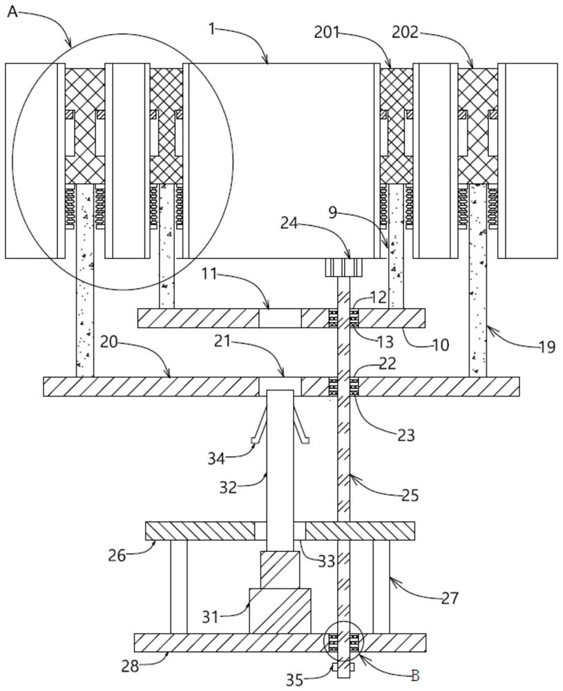
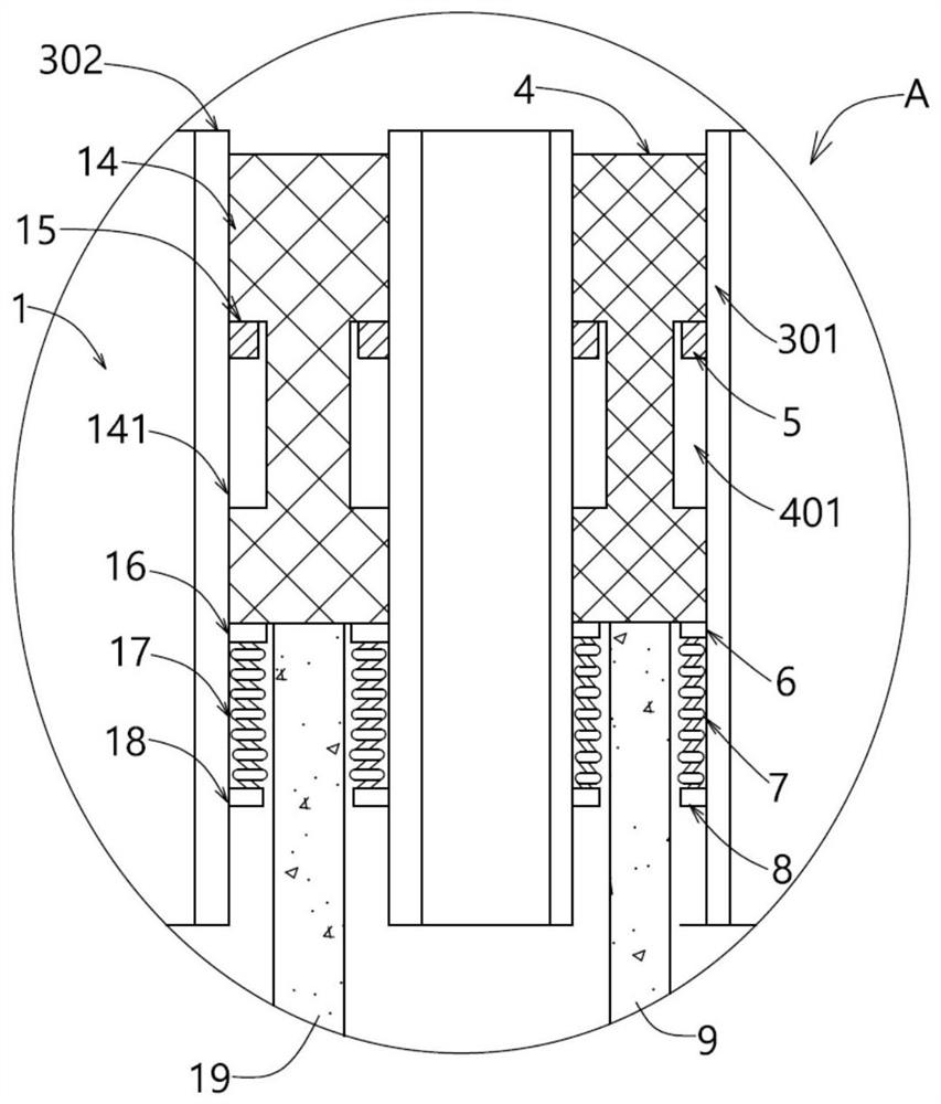
[0046] Embodiment 1: When in use, the movable mold of the injection mold can be fixed on the mounting plate 1. After the injection mold completes the molding process of the injection molded product, it needs to drive the ejector mechanism to eject the injection molded product. At this time, for larger sizes 1. For the injection molding product whose inner hole position of the convex column does not overlap with the second installation groove 202, if the product has lower requirements on machining accuracy, the oil cylinder 31 can be activated, and the oil cylinder 31 will quickly push the drive rod 32 to Move outward, so that the elastic clamping part 34 is inserted into the second clamping hole 21 on the second push plate 20, under the restriction of the second clamping hole 21, due to the second spring 17 compared with the elastic clamping part 34 is more likely to be deformed, so the second push plate 20 is first pushed out outwards, and the second push plate 20 at this time...

Embodiment 2

[0047] Embodiment 2: When in use, the movable mold of the injection mold can be fixed on the mounting plate 1. After the injection mold completes the molding process of the injection molded product, it needs to drive the ejector mechanism to eject the injection molded product. At this time, for smaller size 1. For the injection molding product whose inner hole position of the convex column does not overlap with the first installation groove 201, if the product has lower requirements on machining accuracy, the oil cylinder 31 can still be activated, and the oil cylinder 31 will quickly push the drive rod 32 Move outwards so that the elastic clamping part 34 is engaged in the second engaging hole 21 on the second push plate 20. Under the restriction of the second engaging hole 21, the second spring 17 is more elastically engaged than the second spring 17. Part 34 is more likely to be deformed, and the second push plate 20 is first pushed out outwards. At this time, the second pus...

Embodiment 3

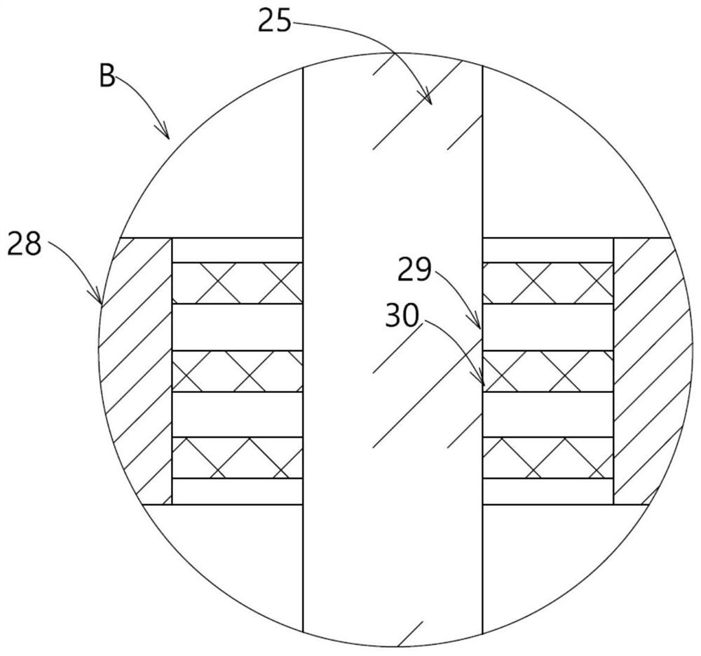
[0048] Embodiment 3: When in use, the movable mold of the injection mold can be fixed on the mounting plate 1. After the injection mold completes the molding process of the injection molded product, it needs to drive the ejector mechanism to eject the injection molded product. At this time, for larger sizes 1. For the injection molding product whose inner hole position of the convex column does not overlap with the second installation groove 202, if the product has higher requirements on machining accuracy, the driving motor 24 can be started, and the driving motor 24 drives the screw 25 to rotate , so that the nut 26 moves slowly along the lead screw 25 to carry out the refined movement of the displacement. The nut 26 drives the base plate 28 to gradually approach the mounting plate 1 through the connecting rod 27, and then the base plate 28 drives the drive rod 32 through the oil cylinder 31, so that The elastic retaining member 34 is engaged in the second engaging hole 21 on...


PUM


Abstract

The invention provides a driving device for an injection molding machine and an injection molding system thereof. The driving device comprises a mounting plate, wherein a first ejector rod is movably arranged in a first mounting groove; a second ejector rod is movably arranged in a second mounting groove; a second cleaning brush is fixedly arranged in a second through hole; a lead screw is fixedly arranged at the output end of a driving motor; a nut is movably arranged on the lead screw; connecting rods are symmetrically and fixedly arranged on one side, far away from the driving motor, of the nut; the connecting rods are fixed on a base plate; an oil cylinder is fixedly arranged on one side, close to the nut, of the base plate; a driving rod is fixedly arranged at the output end of the oil cylinder; and an elastic clamping piece is arranged on the driving rod. According to the driving device for the injection molding machine and the injection molding system thereof, the first ejector rod or the second ejector rod at different positions can be ejected out in an oil cylinder driving mode or a lead screw nut driving mode, multiple driving modes can be realized through mutual combination, the structure is simple, and a user can flexibly select the driving device according to different working conditions.

Description

technical field [0001] The invention relates to the technical field of injection molding machines, in particular to a driving device for an injection molding machine and an injection molding system thereof. Background technique [0002] In the production process of injection molded parts, the injection molded parts must be taken out of the mold cavity. Generally, ejector pins and ejector pins are used to eject the molded plastic parts. However, the existing ejector pin driving device is single and the degree of precision is low. The ejection distance is too large and the plastic parts are damaged, so it needs to be improved. [0003] In the prior art, an ejection mechanism of an injection molding machine with the application number "201810559691.7" relates to the technical field of injection molding machines, including a movable plate, an ejection drive mechanism and a ejector rod assembly. The ejection drive mechanism consists of an ejection cylinder and a The driving guid...

Claims


Application Information

Patent Timeline
IPC IPC(8): B29C45/40
CPCB29C45/4005B29C2045/4036
Inventor 柏松
Owner 柏松
Why Eureka
Try Eureka