Feeding device and feeding method for battery conveying system

A conveying system and battery technology, applied in the direction of transportation and packaging, conveyor objects, etc., can solve the problems of affecting material processing, damage, and inability to be clamped firmly, so as to increase the surface friction coefficient, improve the clamping effect, and improve The effect of clamping suitability

Active Publication Date: 2021-09-24
中科摩通(常州)智能制造股份有限公司
View PDF5 Cites 0 Cited by
  • Summary
  • Abstract
  • Description
  • Claims
  • Application Information

AI Technical Summary

Problems solved by technology

[0003] However, since the clamping surface of the clamping part is a plane parallel to the side wall of the material, when the material is clamped, if the material is not placed vertically in the positioning groove, but slightly inclined, the material will be clamped The tight part cannot be clamped firmly during the clamping process, so it is necessary to design the pressing part to prevent the material from slipping out. However, after the pressing part is installed, the pressing part will push the material toward the material support. If the material cannot be positioned to a certain extent, The material will hit the feeding bracket and cause certain damage, which will affect the subsequent processing of the material

Method used


Image

  • Feeding device and feeding method for battery conveying system
  • Feeding device and feeding method for battery conveying system
  • Feeding device and feeding method for battery conveying system

Examples


Embodiment 1

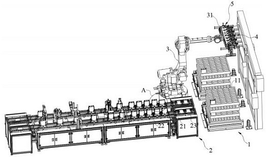
[0035] Such as Figure 1 to Figure 10 As shown, the first embodiment provides a charging device for a battery delivery system, the specific structure includes:

[0036] Incoming material placement mechanism 1,

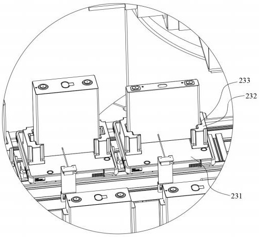
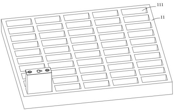
[0037] The incoming material placement mechanism 1 is used as the starting point of the entire battery conveying system, and the tray 11 filled with materials will be transported to the position of the incoming material placement mechanism 1, and the tray 11 with materials is positioned by the incoming material placement mechanism 1, The materials on the tray 11 are clamped and transported backwards for processing. Specifically, a plurality of positioning slots 111 are provided in matrix on the tray 11, and the materials are inserted into the positioning slots 111.

[0038] Feeding and conveying mechanism 2,

[0039]The feeding and conveying mechanism 2 is used as a mechanism for conveying materials backward after feeding, and includes a first conveyor 21 and a secon...

Embodiment 2

[0060] On the basis of Embodiment 1, this Embodiment 2 also provides a charging method for a charging device for a battery conveying system, including a charging device for a battery conveying system in Embodiment 1, wherein a battery conveying The feeding device for the system is the same as the first embodiment, and will not be repeated here.

[0061] A specific loading method of a loading device for a battery delivery system is as follows: after the tray 11 slides into the placement frame 12, the tray 11 is pushed by the side push cylinder 13 to offset the placement frame 12; the loading bracket is driven by the six-axis manipulator 3 31 drives the clamping plate 41 to the corresponding material position; adjusts the direction of the clamping vertical plate 441 and the clamping mounting seat according to the size of the material; drives the two clamping plates 41 to clamp the material through the clamping cylinder 43, and the clamping spring 46 Push the clamping plate 41 to...


PUM


Abstract

The present invention relates to the technical field of lithium batteries, in particular to a feeding device and a feeding method for a battery delivery system, wherein a feeding device for a battery delivery system includes: a six-axis manipulator, a feeding bracket, and several clamping materials The clamping part and the clamping part, as well as the clamping surface of the clamping part, have two opposite clamping plates, the two clamping plates are arranged obliquely and the distance between the two clamping plates is from the side far away from the feeding bracket to close to the feeding One side of the bracket gradually increases; there are several clamping blocks fixedly connected to the end surface of each clamping plate, and the clamping block is located on the side close to the two clamping plates; the ring six-axis manipulator is equipped with an incoming material placement mechanism and an upper Material conveying mechanism and incoming material placement mechanism are suitable for placing trays with materials; when the six-axis manipulator is located in the area of ​​the incoming material placement mechanism, the two clamping plates can be rotated to be parallel to the outer side walls of the material; after the material is clamped by the two clamping plates , the pressing part can push the material to offset against the clamping block, so that the clamping block can position the material.

Description

technical field [0001] The invention relates to the technical field of lithium batteries, in particular to a feeding device and a feeding method for a battery delivery system. Background technique [0002] In the prior art, the pallet with material sent from the front end is sent to the feeding conveying mechanism through the six-axis manipulator after the material is clamped to complete the feeding, and the material is sent to the follow-up through the feeding conveying mechanism. The process is conveyed. [0003] However, since the clamping surface of the clamping part is a plane parallel to the side wall of the material, when the material is clamped, if the material is not placed vertically in the positioning groove, but slightly inclined, the material will be clamped The tight part cannot be clamped firmly during the clamping process, so it is necessary to design the pressing part to prevent the material from slipping out. However, after the pressing part is installed, ...

Claims


Application Information

Patent Timeline
Patent Type & Authority Patents(China)
IPC IPC(8): B65G47/91B65G47/22
CPCB65G47/22B65G47/914
Inventor 赵丹
Owner 中科摩通(常州)智能制造股份有限公司
Why Eureka
Try Eureka