
Light steel frame bridge structure and erecting method thereof

A steel frame bridge, lightweight technology, applied in bridge construction, erection/assembly of bridges, bridges, etc., can solve the problems of bridge welding structure failure, increase the difficulty of bridge construction, and cannot well reflect the lightweight characteristics of steel bridges, etc. Achieve the effect of increasing the shock absorption effect and reducing the difficulty of erection

Inactive Publication Date: 2021-07-23
闫军涛
View PDF0 Cites 0 Cited by
  • Summary
  • Abstract
  • Description
  • Claims
  • Application Information

AI Technical Summary

Problems solved by technology

[0003] 1. The existing steel bridge is pulled by zipper to increase its load-bearing capacity, but when the steel bridge is pulled by zipper structure, the bridge has high construction requirements for the bridge pier during erection. Although the span can be increased, but It will increase the difficulty of bridge construction, cannot well reflect the light characteristics of steel bridges, and increase the difficulty of erection
[0004] 2. The supporting structure of the existing steel bridge mainly relies on the pier at the bottom. When the light steel bridge in the city is built, the steel frame pier structure will reduce the load-bearing capacity of the steel bridge and the span length of the bridge. At the same time, the light steel structure The bridge adopts a welded structure to connect the bridge deck and the bridge's support structure, which will reduce the shock absorption effect of the bridge, and the welded structure of the bridge will fail if used for a long time

Method used


Image

  • Light steel frame bridge structure and erecting method thereof
  • Light steel frame bridge structure and erecting method thereof
  • Light steel frame bridge structure and erecting method thereof

Examples


Embodiment Construction

[0048] The following will clearly and completely describe the technical solutions in the embodiments of the present invention with reference to the accompanying drawings in the embodiments of the present invention. Obviously, the described embodiments are only some, not all, embodiments of the present invention. Based on the embodiments of the present invention, all other embodiments obtained by persons of ordinary skill in the art without making creative efforts belong to the protection scope of the present invention.

[0049]In the description of the present invention, it should be noted that the terms "upper", "lower", "inner", "outer", "front end", "rear end", "both ends", "one end", "another end" The orientation or positional relationship indicated by etc. is based on the orientation or positional relationship shown in the drawings, and is only for the convenience of describing the present invention and simplifying the description, rather than indicating or implying that t...


PUM


Abstract

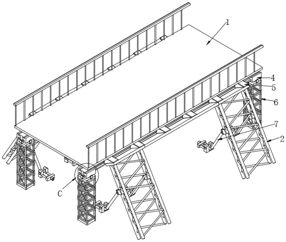
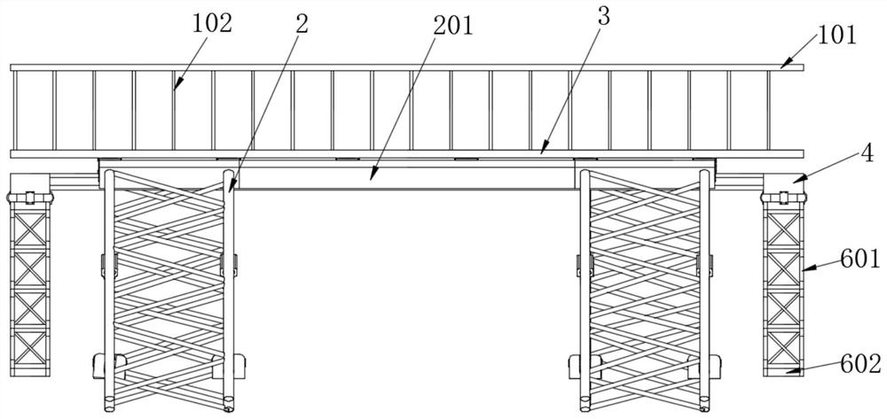
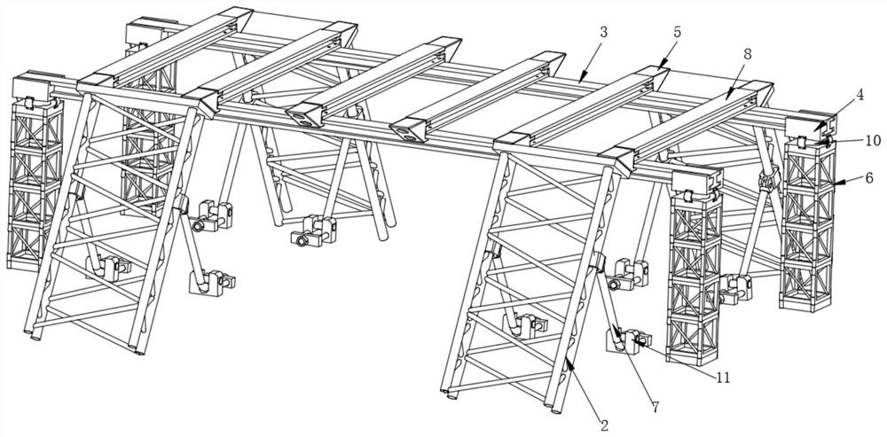
The invention discloses a light steel frame bridge structure and an erecting method thereof. The light steel frame bridge structure comprises a bridge floor, inclined supporting units and bridge piers. Main I-shaped steel is installed on the two sides of the bottom of the bridge floor, shock absorbers are installed at the bottoms of the two ends of the main I-shaped steel, bridge piers are arranged at the bottoms of the shock absorbers, inclined supporting units are installed at the two ends of the main I-shaped steel, and tensioning steel ropes are installed on the two sides of each inclined supporting unit; the end, away from the inclined supporting unit, of the tensioning steel rope is connected with a U-shaped tensioning foundation anchor. The main I-shaped steel and the auxiliary I-shaped steel are staggered to construct the bridge deck structure, then the four sets of inclined supporting units are obliquely installed at the bottom of the bridge deck structure, the inclined supporting units share the load of the bridge pier structure, a steel frame supporting structure is adopted to replace a zipper structure, the erecting difficulty is reduced, and through combined use of the tensioning ropes and the inclined supporting units, the damping effect of the bridge is improved, the bridge bearing structure is connected in a split mode, and it is guaranteed that the bridge steel structure cannot lose efficacy when used for a long time.

Description

technical field [0001] The invention relates to the technical field of bridges, in particular to a light steel bridge structure and an erection method thereof. Background technique [0002] A steel bridge is a bridge made of steel with a bridge span structure. In 1874, the United States built the world's first large steel bridge on the Mississippi River - the St.Louis (St.Louis) steel arch bridge. After World War II, the steel bridge Science and technology have made great progress in the smelting of high-strength and high-quality steel, the improvement of welding technology, the application of orthotropic steel bridge decks and high-strength bolts, and the diversification of structural types, etc., which have promoted the wide adoption of long-span steel bridges . [0003] 1. The existing steel bridge is pulled by zipper to increase its load-bearing capacity, but when the steel bridge is pulled by zipper structure, the bridge has high construction requirements for the bridg...

Claims


Application Information

Patent Timeline
Patent Type & Authority Applications(China)
IPC IPC(8): E01D1/00E01D2/02E01D19/12E01D19/10E01D19/02E01D21/00E01D101/30
CPCE01D1/00E01D2/02E01D19/02E01D19/103E01D19/125E01D21/00E01D2101/30
Inventor 闫军涛黄文明张晓林程昊秦桂枝夏李阳白伟辉詹丽娜宋亚攀任洪涛
Owner 闫军涛
Learn More