High-voltage transformer for TV. receiver

A technology of high-voltage transformers and television receivers, which is applied in the field of high-voltage transformers, can solve the problems of high cost, and achieve the effects of capacity improvement, cost reduction, and good transformer coupling

Inactive Publication Date: 2003-12-17
DEUTSCHE THOMSON-BRANDT GMBH
View PDF2 Cites 0 Cited by
  • Summary
  • Abstract
  • Description
  • Claims
  • Application Information

AI Technical Summary

Problems solved by technology

However, primary windings made with multi-strand wire are seven times more expensive than single-stra

Method used


Image

  • High-voltage transformer for TV. receiver
  • High-voltage transformer for TV. receiver
  • High-voltage transformer for TV. receiver

Examples


Embodiment Construction

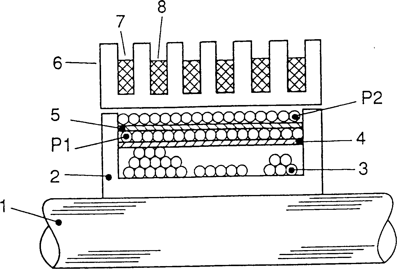
[0016] figure 1 Shown is a core leg 1 of a high voltage transformer core. The core is preferably designed as a U / U core, E / I core or U / I core. The coil former 2 is placed on the core leg 1 . First, located at the bottom of the bobbin 2 are a plurality of auxiliary windings 3, which are used, for example, to generate operating voltage, pulse voltage, or heating of the picture tube. The auxiliary winding 3 has an uneven surface. For this reason, a bushing 4 made of a dielectric material and having a wall thickness of eg 0.4 to 0.8 mm is placed on the auxiliary winding 3 , which bushing forms a smooth bottom layer of the primary winding. The first element P1 of the primary winding is first placed on the bushing 4 in the form of a coil layer. The winding unit P1 is wound in a bifilar manner with a double enamelled copper wire (CuEE) having a diameter of 2×0.45 mm. Another bushing 5 is placed on the winding unit P1. The second element P2 of the primary winding connected in se...


PUM


Abstract

The invention relates to a high voltage transformer for TV receiver, a primary winding P is wound by single strand wire layers P1 and P2 where one layer is placed flatly on another layer, besides a lining 5 made of medium is arranged between each two layers, single strand wires are adopted in place of traditional multi-strand wires, so that the cost of the primary winding is reduced by 7 times and can meet the requirements of coupling, copper loss and skin loss. The high voltage transformer is in particular applied in the TV receiver with row frequency enhanced to 32KHz.

Description

technical field [0001] The invention relates to a high-voltage transformer, in particular to a high-voltage transformer in which single-strand wires can be used instead of multi-strand wires for the primary winding of a television receiver. Background technique [0002] The invention relates to a high-voltage transformer of a television receiver. In transformers of this type, it is well known to use strands of wire to wind the primary winding. In order to keep the so-called skin loss low enough, the primary winding must use multi-strand wire, which is especially necessary for the relatively high 32kHz horizontal frequency. However, primary windings made with stranded wire are seven times more expensive than single-stranded wire and have disadvantages in winding operations, soldering, and fixing to transformer terminals. Contents of the invention [0003] The purpose of the present invention is to design a high-voltage transformer for television receivers, so that the pri...

Claims


Application Information

Patent Timeline
IPC IPC(8): H01F38/42
CPCH01F38/42H01F2005/022
Inventor 沃尔特·戈斯伯格
Owner DEUTSCHE THOMSON-BRANDT GMBH
Why Eureka
Try Eureka