Supercharge Your Innovation With Domain-Expert AI Agents!

Battery module

A technology for battery modules and battery packs, which is applied to battery pack components, circuits, electrical components, etc., can solve problems such as large numbers and complicated process assembly, and achieve the effects of simplifying assembly processes, reducing costs, and reducing manufacturing costs.

Active Publication Date: 2021-07-23
ZHEJIANG LEAPMOTOR TECH CO LTD
View PDF11 Cites 0 Cited by
  • Summary
  • Abstract
  • Description
  • Claims
  • Application Information

AI Technical Summary

Problems solved by technology

[0007] The present invention mainly solves the problems in the prior art that the battery modules have a large number of structure types and quantities, and the process assembly is cumbersome; it provides a battery module, reduces the number of module components, and reduces the cost

Method used


Image

  • Battery module
  • Battery module
  • Battery module

Examples


Embodiment 1

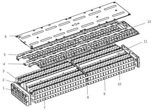
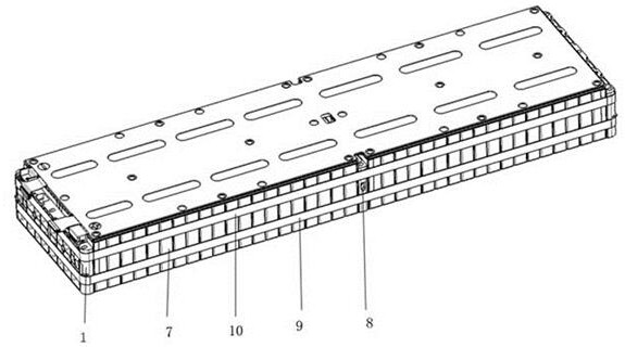
[0022] Embodiment 1: a battery module, such as figure 1 and figure 2 As shown, it includes battery pack, two end insulating sheets 2, two fixed end plates 1, cover plate 6, plastic bracket 1312, output pole 3, FPC4, bus aluminum sheet 5, plastic strap 9, metal strap 10 and a reinforcing plate 8, the battery pack includes four cell groups 7, each cell group 7 includes several single cells, and the single cells are bonded by glue to form a cell group 7, 4 cell groups 7 is arranged in double rows, the intermediate insulating sheet 11 is arranged between the two rows of cell groups 7, the reinforcement plate 8 is arranged between the two rows of cell groups 7, and the two fixed end plates 1 clamp and fix the battery group, The end insulating sheet 2 is installed between the fixed end plate 1 and the battery pack. The four cell packs 7 are bound by the metal strap 10 and the plastic strap 9 to form a whole battery pack. The plastic bracket 1312 is installed on the upper end of th...

Embodiment 2

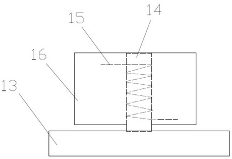
[0023] Embodiment 2, a battery module, such as image 3 As shown, the difference between the present embodiment and the first embodiment is that the reinforcing plate 8 of the present embodiment includes a base, a fixed rod 14, a torsion spring 15 and a movable plate 16, the base is installed between the battery packs 7, and the fixed rod 14 is fixedly installed on the base, the torsion spring 15 is installed on the fixed rod 14, the movable plate 16 is provided with a mounting groove matching the torsion spring 15, and the movable plate 16 is movably installed on the fixed rod 14 through the matching connection of the mounting groove and the torsion spring 15 Above, the cover plate 6 is also provided with a limit hole matching the cover plate 6 , and the elastic potential energy of the torsion spring 15 is smaller than that of the plastic strap 9 . All the other structures are the same as in Embodiment 1.

[0024] In a specific application, glue is first applied to each sing...


PUM


Abstract

The invention discloses a battery module, comprising: a plurality of battery cell groups, of which each comprises a plurality of single battery cells and is used for providing electric energy; a confluence aluminum sheet which is used for connecting and conducting the plurality of single battery cells and is connected with the battery cell groups; an output pole column which is used for outputting the electric energy stored in the battery cell groups and is connected with the confluence aluminum sheet; and a fixing device which is used for fixing the plurality of battery cell groups to form a battery module. A module aluminum side plate is omitted, the module is fixed and restrained through a metal binding band and a plastic binding band, welding is not needed, direct assembly is achieved, the assembly process of the module is simplified, and the manufacturing cost is reduced. A double-row battery cell arrangement form is used, so that the size of the module is increased, the number of structural members of the module are reduced, and the structural member cost of the module is reduced. One battery pack can contain more single cells, the number of modules is greatly reduced, connecting copper bars between the modules are reduced, and the cost of the whole battery pack system is reduced.

Description

technical field [0001] The invention relates to the technical field of batteries, in particular to a battery module. Background technique [0002] With the layout of the domestic new energy vehicle industry gradually forming a scale, the industry has gradually matured from rising to maturity, and the state has gradually reduced subsidies for new energy companies, posing greater challenges to the survival of new energy companies. If new energy vehicles want to be accepted by the public, they must solve the concerns of consumers, one is the battery life, the other is the convenience of charging, and of course the cost performance. At present, the main concern of everyone is the battery life of new energy vehicles. Whether it can be like traditional gasoline vehicles without worrying about its mileage. [0003] As we all know, a battery pack system is roughly composed of battery modules, battery boxes, thermal management systems, battery control systems (BMS) and other compone...

Claims


Application Information

Patent Timeline
Patent Type & Authority Applications(China)
IPC IPC(8): H01M50/249H01M50/258H01M50/244H01M50/502H01M50/505
CPCY02E60/10
Inventor 强心双宋忆宁蔡建军苏立擂
Owner ZHEJIANG LEAPMOTOR TECH CO LTD
Features
  • R&D
  • Intellectual Property
  • Life Sciences
  • Materials
  • Tech Scout
  • Unparalleled Data Quality
  • Higher Quality Content
  • 60% Fewer Hallucinations
Learn More