High-power variable-dip-angle continuous section node array antenna

An array antenna, high-power technology, applied in specific array feeding systems, antennas, antenna arrays, etc. Strong distance communication capability, long antenna action distance, safe and effective transmission effect

Inactive Publication Date: 2021-07-23
XIDIAN UNIV
View PDF11 Cites 1 Cited by
  • Summary
  • Abstract
  • Description
  • Claims
  • Application Information

AI Technical Summary

Problems solved by technology

However, its antenna structure cannot meet the requirements of high power
[0007] Application publication number CN 105655720 A discloses a high-gain VICTS antenna, which uses a parabolic reflector and a serial feed to excite VICTS, but the radiation slots of the flat CTS are equal in length and the feeding base is rectangular, which is not conducive to the etching of the slots. The relative rotation between the disk and the feeder base plate is used to realize the beam scanning of the elevation plane; in addition, if the high-power energy is input from the main port in the serial feed mode, the antenna is easily broken down, so the antenna cannot meet the high-power requirements
[0008] Application publication number CN 106992354 A discloses a sub-array feeding VICTS satellite communication antenna, which adopts a scheme of dividing the circular VICTS into multiple sub-arrays along the propagation direction and feeding them separately. Although

Method used


Image

  • High-power variable-dip-angle continuous section node array antenna
  • High-power variable-dip-angle continuous section node array antenna
  • High-power variable-dip-angle continuous section node array antenna

Examples


Embodiment Construction

[0033] The specific embodiments and effects of the present invention will be further described in detail below with reference to the accompanying drawings.

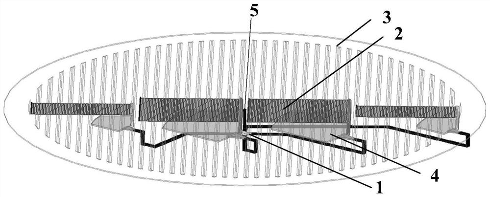
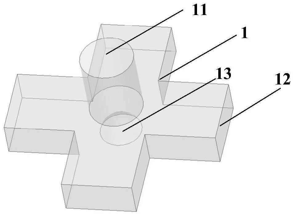
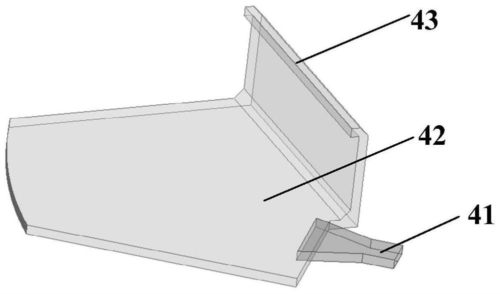
[0034] Refer figure 1 This example includes a power divider 1, a lower metal feed base plate 2, an upper metal disc 3, a bias parabolic reflection cartridge 4. The power divider 1 is located directly below the center of the lower metal feed base plate 2 and the upper metal disc 3, and there are a plurality of output terminals, respectively, respectively, by the H-surface turning waveguide, respectively, parabolic reflection box 4 The lower metal feed base plate 2 is divided into several sub-array along the propagation direction, and the present example is divided into four sub-array; the upper metal disc 3 is provided with a rotating joint 5 between the lower metal feed base plate 2, and is located on the upper metal The central position of the disc 3 is to ensure that the lower metal feed base plate 2 and the upper metal dis...


PUM


Abstract

The invention discloses a high-power variable-dip-angle continuous section node array antenna, and mainly solves the problem that the existing similar antennas do not have high-power performance. The antenna comprises a power divider (1), a lower-layer metal feed base plate (2) and an upper-layer metal disc (3), wherein the power divider is located under the circle center position of the lower-layer metal feed base plate and the circle center position of the upper-layer metal disc, and the output end of the power divider is connected with a plurality of bias parabolic reflection boxes (4) to form an antenna feed link; The lower-layer metal feed base plate is split into a plurality of sub-arrays along the propagation direction to feed respectively, the wide side of each sub-array has at least 10 wavelengths, and the narrow side of each sub-array has no more than 2 wavelengths; and a rotary joint (5) is arranged between the upper-layer metal disc and the lower-layer metal feed base plate so as to realize relative rotation of the upper-layer metal disc and the lower-layer metal feed base plate. On the basis of ensuring continuous scanning of the variable-dip-angle continuous section node array antenna, high-power performance is achieved, the operating distance is increased, and the antenna can be used for high-power and long-distance communication of satellites and radars.

Description

Technical field [0001] The present invention belongs to the field of antenna technology, and in particular, the present invention relates to a variable tilt-in continuous sectional array antenna, which can be used for high power and long-distance communication of satellite, radar. Background technique [0002] With the continuous improvement of science and technology, my country's satellite communication technology has also achieved great achievements, and satellite communication has the advantages of high communication distance, flexible, and large communication capacity. In order to meet the needs of the satellite communication system, the antenna used is higher requirements. [0003] On the one hand, since the long-distance communication has a large loss during the transmission process, in order to make up for the transmission loss, the satellite communication is highly required for the ground emission antenna action distance; and the radar also requires a large detection radi...

Claims


Application Information

Patent Timeline
IPC IPC(8): H01Q21/00H01Q1/50H01Q15/16H01P5/18
CPCH01Q21/0006H01Q1/50H01Q15/16H01P5/188
Inventor 翁子彬刘向搏张立焦永昌赵钢李雨桐
Owner XIDIAN UNIV
Why Eureka
Try Eureka