Check patentability & draft patents in minutes with Patsnap Eureka AI!

Sensorless control method and device for permanent magnet synchronous motor

A permanent magnet synchronous motor and control method technology, applied in the aerospace field, can solve problems such as difficulty in adding circuits, failure of mechanism movement functions, no backup of sensors, etc., and achieve the effect of reducing hardware complexity

Active Publication Date: 2021-07-23
BEIJING INST OF SPACECRAFT SYST ENG
View PDF7 Cites 0 Cited by
  • Summary
  • Abstract
  • Description
  • Claims
  • Application Information

AI Technical Summary

Problems solved by technology

In the field of aerospace, due to the requirement of spacecraft weight reduction design, the sensor often has no backup. Therefore, when the sensor fails, the motor will not be able to operate in the normal mode, resulting in the failure of the mechanism’s motion function and affecting the completion of the mission of the spacecraft.
[0003] The patent "A Motor Sensorless Drive Control System" with publication number CN104167961A proposes a drive circuit and control method for high-speed motors (rotating speed 10,000rpm-120,000rpm). However, the drive circuit proposed in this patent must have a dedicated However, the controller of the spacecraft motor is limited by the size and power consumption, so it is difficult to increase the circuit. At the same time, the speed of the spacecraft motor is generally only between 300 and 1200rpm, so this patent cannot solve the problem of the spacecraft motor. Technical Difficulties of Sensorless Control

Method used


Image

  • Sensorless control method and device for permanent magnet synchronous motor
  • Sensorless control method and device for permanent magnet synchronous motor
  • Sensorless control method and device for permanent magnet synchronous motor

Examples


Embodiment Construction

[0057] The present invention will be described in detail below with reference to the accompanying drawings and examples.

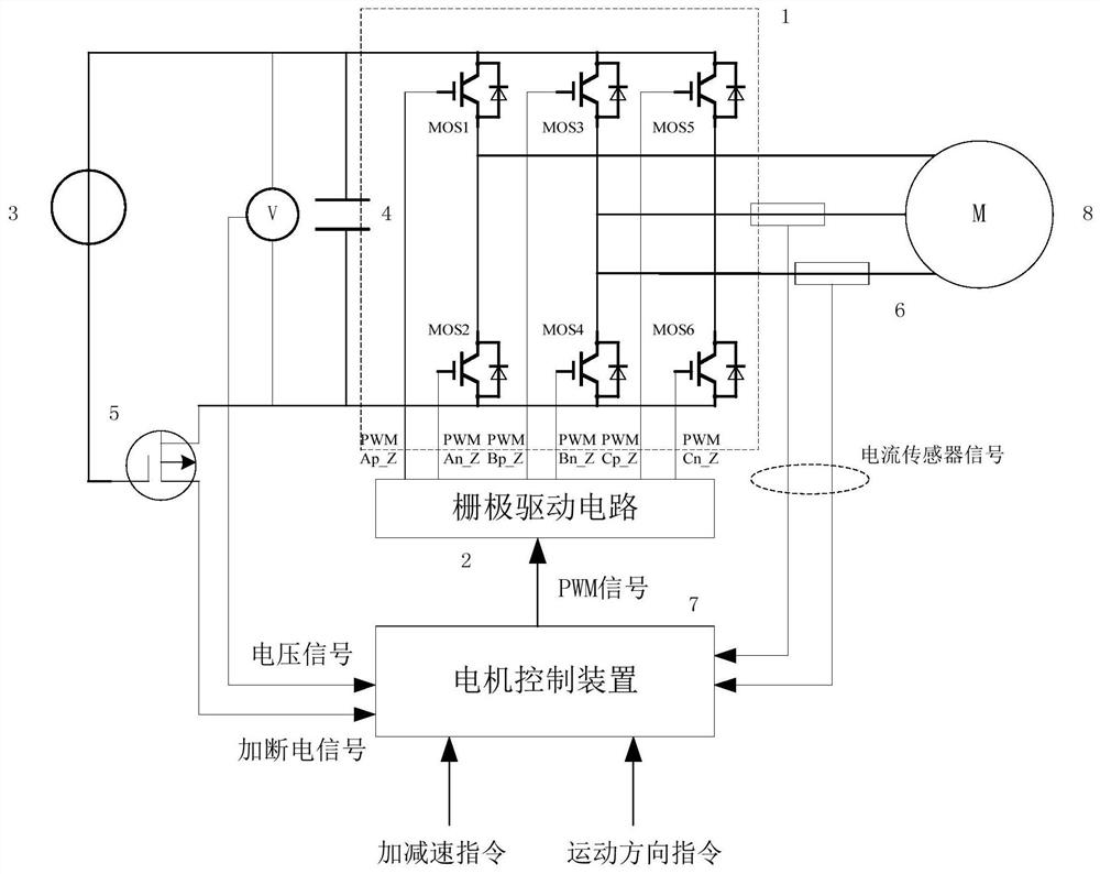
[0058] The structure of the permanent magnet synchronous motor driving device corresponding to the method of the present invention is as follows: figure 1 As shown, it includes a bridge circuit 1 , a gate drive circuit 2 , a voltage source 3 , a voltage stabilizing capacitor 4 , a power-on / off MOS tube 5 , a current sensor 6 , a motor controller 7 , a motor 8 , and a voltage detection device 9 . The voltage source 3 supplies the DC voltage of the voltage source 3 to the bridge circuit 1 and the voltage stabilizing capacitor 4 via the power-on / off MOS transistor 5 . The bridge circuit 1 performs power conversion between the voltage source 3 and the motor 8, and converts the DC voltage of the voltage source 3 into U, V, and W phase voltages. The bridge circuit 1 is composed of a plurality of switching elements MOS1-MOS6. The drain of MOS transistor 1 is co...


PUM


Abstract

The invention discloses a sensorless control method and device for a permanent magnet synchronous motor. A motor rotor position sensor and a back electromotive force detection circuit are not needed in the control process, and the hardware complexity is reduced; acceleration and deceleration control of the motor rotor is realized by generating a rotating stator magnetic field with an adjustable amplitude, and the motor can still run normally without a motor rotor position sensor; the angle of the motor is calculated by detecting the change of a flux linkage sector, the rotating speed of the motor is calculated through difference and smooth filtering, and the rotating speed information of the motor can still be obtained without a motor rotor position sensor. According to the method, the flux linkage angle is calculated by measuring the two-phase winding current in the three-phase motor, and the flux linkage sector is judged according to the flux linkage angle; a PWM signal is generated according to the flux linkage sector, the rotation direction instruction and the acceleration and deceleration instruction, a motor stator winding generates a rotating magnetic field, the rotation of the motor is controlled, the rotation speed of the motor is calculated according to the change of the flux linkage sector, and the rotation speed is outputted through smooth filtering.

Description

technical field [0001] The invention belongs to the aerospace field and relates to a sensorless control method and device for a permanent magnet synchronous motor. Background technique [0002] At present, servo motors represented by permanent magnet synchronous motors are equipped with rotor position sensors on the motor shaft, which are not only used to measure the motor speed but also provide input signals for motor drive control. In the field of aerospace, due to the requirement of spacecraft weight reduction design, the sensor often has no backup. Therefore, when the sensor fails, the motor will not be able to operate in the normal mode, resulting in the failure of the mechanism’s motion function and affecting the completion of the spacecraft’s mission. [0003] The patent "A Motor Sensorless Drive Control System" with publication number CN104167961A proposes a drive circuit and control method for high-speed motors (rotating speed 10,000rpm-120,000rpm). However, the dri...

Claims


Application Information

Patent Timeline
IPC IPC(8): H02P6/18H02P23/14H02P25/022
CPCH02P6/18H02P23/14H02P25/022H02P2207/05
Inventor 张沛周东王康梁常春姜水清马如奇林云成刘鑫
Owner BEIJING INST OF SPACECRAFT SYST ENG
Features
  • R&D
  • Intellectual Property
  • Life Sciences
  • Materials
  • Tech Scout
  • Unparalleled Data Quality
  • Higher Quality Content
  • 60% Fewer Hallucinations
Learn More