Closed impeller and manufacturing method thereof
The technology of a closed impeller and a manufacturing method can be applied to manufacturing tools, non-variable-capacity pumps, liquid fuel engines, etc., and can solve the problems of high manufacturing costs, easy residual molten metal, and reduced operating efficiency of centrifugal compressors. The effect of high bonding strength
- Summary
- Abstract
- Description
- Claims
- Application Information
AI Technical Summary
Problems solved by technology
Method used
Image

Examples
Embodiment 1
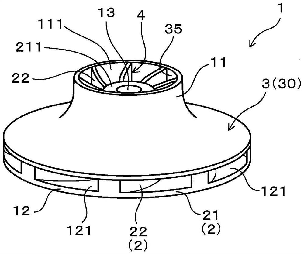
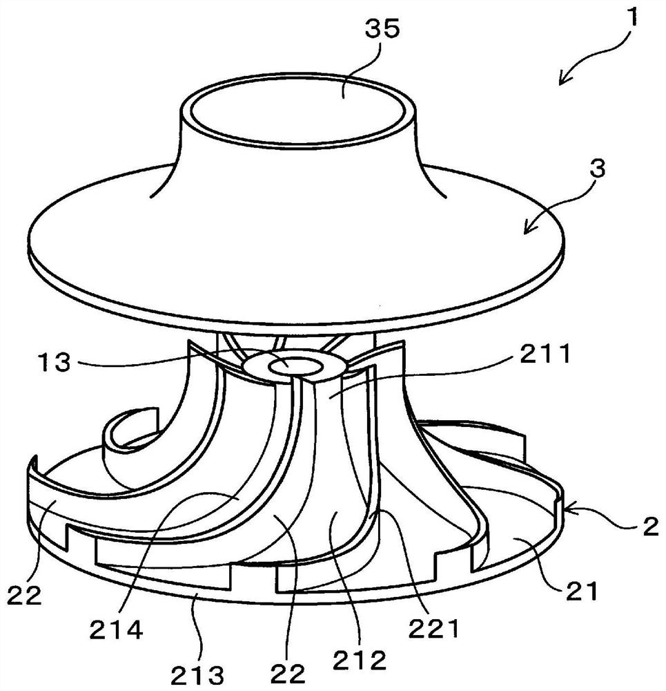
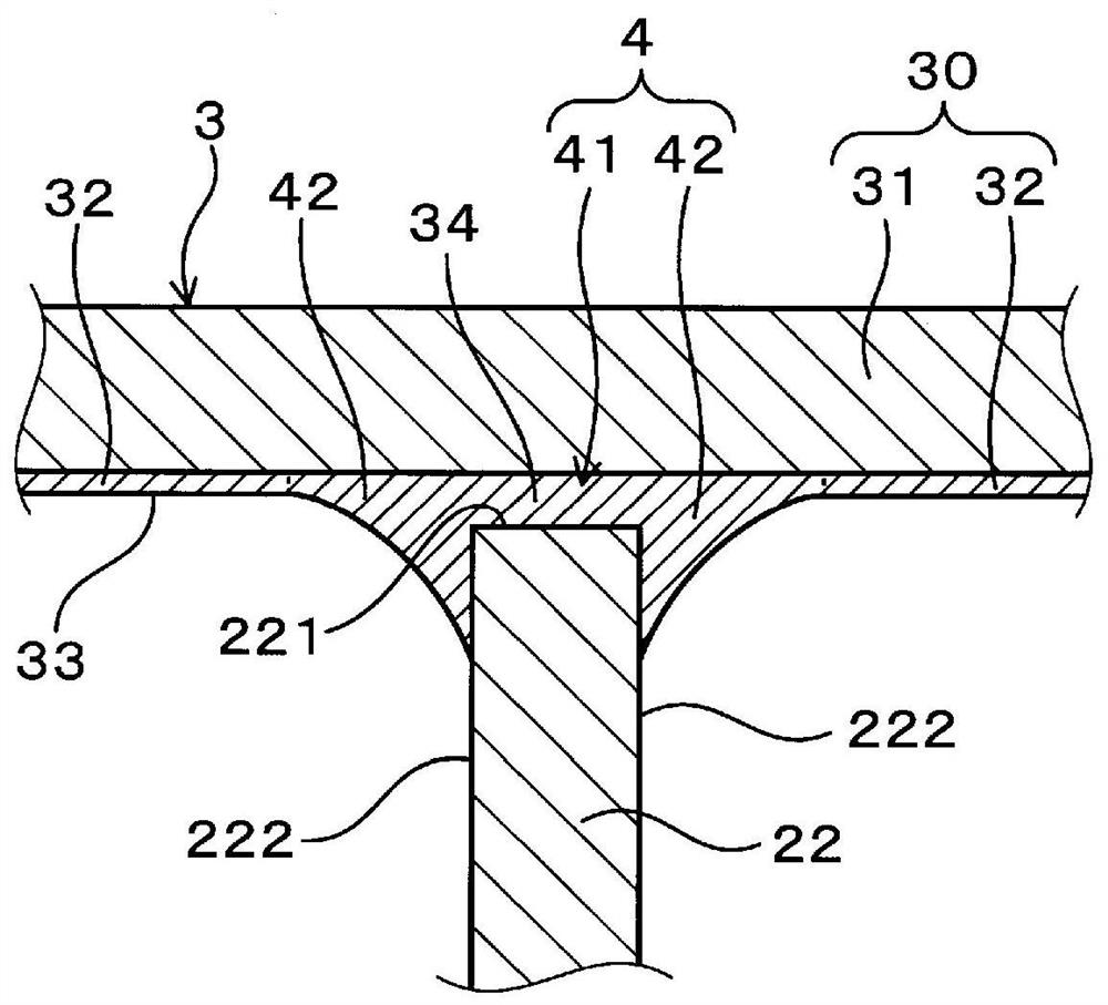
[0078] use Figure 1 to Figure 4 Examples of the above-mentioned hermetic impeller and its manufacturing method will be described. Such as figure 1 and figure 2 As shown, the hermetic impeller 1 has: an impeller body 2 made of aluminum alloy, and includes a hub portion 21 and a blade portion 22 protruding from the hub portion 21 ; and a shroud 3 covering the blade portion 22 . Such as image 3 As shown, the blade portion 22 and the shroud 3 are joined by a brazed joint 4 interposed between the blade portion 22 and the shroud 3 . In addition, the shroud 3 is a brazing sheet 30 including a core material 31 made of an aluminum alloy and a brazing material layer 32 disposed on the core material 31 and existing opposite to the blade portion 22 . 33 of the most surface. In addition, below, the outermost surface 33 of the shroud 3 which opposes the blade part 22 is called "the inner surface 33 of the shroud 3."
[0079] Such as figure 1 As shown, the hermetic impeller 1 of th...
Embodiment 2
[0097] This example is an example in which the bonding strength of the brazed joint 4 formed between the shroud 3 and the blade portion 22 is evaluated using the test piece 100 simulating the shapes of the shroud 3 and the blade portion 22 . In addition, unless otherwise specified, among the symbols used in this example and subsequent embodiments, the same symbols as those used in the conventional examples represent the same components and the like as the conventional examples.
[0098] Such as Figure 5 As shown, the test piece 100 used in this example has a first member 101 simulating the blade portion 22 and a second member 102 simulating the shroud 3 . The first member 101 is a flat plate made of JIS A6061 alloy and having a thickness of 3 mm. In addition, the second member 102 is a brazing sheet 300 (test materials 1 to 21) having a thickness of 2 mm and having a laminated structure shown in Table 1.
[0099] In addition, the symbol "Bal." in Table 1 is a symbol indicat...
Embodiment 3
[0120] This example is an example of evaluating the brazability when the impeller body 2 made of JIS A6061 alloy and the shroud 3 made of the test materials shown in Table 1 are brazed. In this example, first, a block of JIS A6061 alloy was subjected to cutting processing to produce an impeller body 2 with an outer diameter of 40 mm. Then, using the test materials shown in Table 1, the shroud 3 corresponding to the impeller body 2 was fabricated. These impeller main bodies 2 and shroud 3 were brazed by the method described in Example 2 to obtain a hermetic impeller 1 .
[0121] The evaluation of solderability can be performed based on the shape of the fillet 42 formed in the solder joint 4 and the occurrence state of joint defects in the solder joint 4 . When evaluating the shape of the fillets 42 , first, the hermetic impeller 1 after brazing was cut. Then, the shape of the fillet 42 of the solder joint 4 visible from the cut portion was observed. The meanings of the symbo...
PUM
| Property | Measurement | Unit |
|---|---|---|
| Bond strength | aaaaa | aaaaa |
| Thickness | aaaaa | aaaaa |
| Thickness | aaaaa | aaaaa |
Abstract
Description
Claims
Application Information