Laser transmitting and receiving system, laser radar and automatic driving equipment

A technology of laser transceiver and laser radar, which is applied in the field of radar, can solve the problems of light energy loss and unutilized light energy, and achieve the effect of improving utilization rate, increasing signal light energy value, and reducing light source power

Pending Publication Date: 2021-07-23
SUTENG INNOVATION TECH CO LTD
View PDF0 Cites 0 Cited by
  • Summary
  • Abstract
  • Description
  • Claims
  • Application Information

AI Technical Summary

Problems solved by technology

The conventional array detector directly uses the flood light source obtained by shaping the signal light source for illumination, resulting in a large loss of light energy received by the photosensitive area of ​​th

Method used


Image

  • Laser transmitting and receiving system, laser radar and automatic driving equipment
  • Laser transmitting and receiving system, laser radar and automatic driving equipment
  • Laser transmitting and receiving system, laser radar and automatic driving equipment

Examples


Example Embodiment

[0037] Embodiments of the technical solutions of the present invention will be described in detail below in conjunction with the accompanying drawings. The following examples are only used to illustrate the technical solution of the present invention more clearly, so they are only examples, and should not be used to limit the protection scope of the present invention.

[0038] It should be noted that, unless otherwise specified, the technical terms or scientific terms used in the present invention shall have the usual meanings understood by those skilled in the art to which the present invention belongs.

[0039] In describing the present invention, it is to be understood that the terms "center", "longitudinal", "transverse", "length", "width", "thickness", "upper", "lower", "front", " Back", "Left", "Right", "Vertical", "Horizontal", "Top", "Bottom", "Inner", "Outer", "Clockwise", "Counterclockwise", "Axial", " The orientation or positional relationship indicated by "radial"...


PUM


Abstract

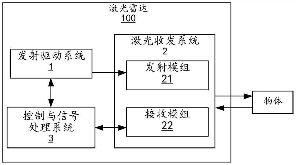
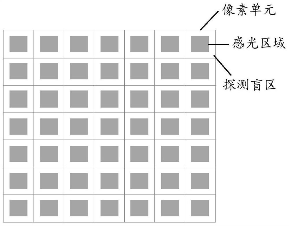
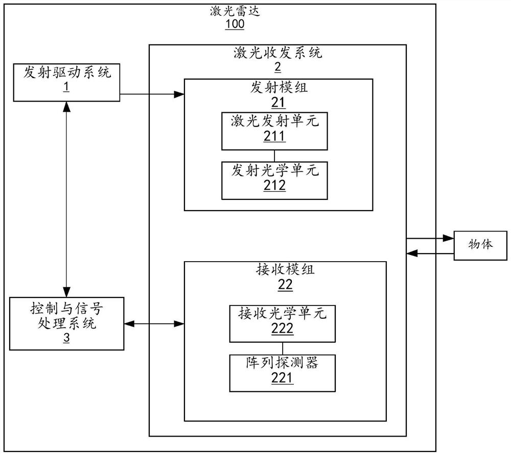
The present invention provides a laser transmit-receive system (2), a laser radar (100), and an automatic driving apparatus (200). The laser transceiving system (2) comprises a transmitting module (21) and a receiving module (22); the emission module (21) comprises a laser emission unit (211) and an emission optical unit (212); the receiving module (22) comprises an array detector (221), the array detector (221) comprises a plurality of pixel units, and each pixel unit is internally provided with a photosensitive area with the area smaller than that of the pixel unit; the laser emitting unit (211) is used for emitting emergent laser; the emission optical unit (212) is used for enabling the emergent laser to form a plurality of emergent laser beams corresponding to the photosensitive area and enabling the emergent laser beams to be emitted to the detection area; each light sensing area in the receiving module (22) is used for receiving an echo laser beam returned after the emergent laser beam corresponding to the light sensing area is reflected by an object in the detection area. The laser transmit-receive system (2) improves the utilization rate of signal light.

Description

technical field [0001] The embodiments of the present invention relate to the technical field of radar, and in particular to a laser transceiver system, a laser radar, and an automatic driving device. Background technique [0002] The existing laser transceiver system using array detection mainly includes signal light source and related drive, beam shaping system, beam deflection system, receiving antenna (also called receiving lens), array detector, control and signal processing system, etc. Its detection distance is mainly limited by factors such as the clear aperture of the receiving lens, the transmitting power of the signal light source, and the fill factor of the array detector (that is, the ratio of the photosensitive area to the entire pixel area). [0003] In a single pixel of a conventional array detector, in addition to the photosensitive area, there are some integrated circuits, multi-layer wiring, and increased spacing for anti-crosstalk factors between pixels. ...

Claims


Application Information

Patent Timeline
IPC IPC(8): G01S7/481
CPCG01S7/481G01S17/88G01S17/93
Inventor 马丁昽
Owner SUTENG INNOVATION TECH CO LTD
Why Eureka
Try Eureka