
Integrated hydraulic system and tire vulcanizing machine

A hydraulic system and integrated technology, applied in the field of tire building, can solve the problems of increased energy consumption and cost, many pipeline connection points, and high use cost, and achieve the effects of compact structure, fewer pipeline connection points, and low leakage probability.

Pending Publication Date: 2021-07-27
SAFE RUN & HISCENT MACHINERY SUZHOU
View PDF0 Cites 1 Cited by
  • Summary
  • Abstract
  • Description
  • Claims
  • Application Information

AI Technical Summary

Problems solved by technology

[0003] The existing hydraulic vulcanizers have the following disadvantages: the mold opening and closing cylinder and the pressurizing cylinder are two independent cylinders, resulting in high cost of use, large space occupation, cumbersome installation, many pipeline connection points, and leakage points of hydraulic oil. It increases accordingly; the mold opening and closing cylinder realizes rapid mold closing all rely on the output flow of the pump, the displacement of the pump is large, and the power of the matching motor is also large, which increases energy consumption and cost

Method used


Image

  • Integrated hydraulic system and tire vulcanizing machine
  • Integrated hydraulic system and tire vulcanizing machine
  • Integrated hydraulic system and tire vulcanizing machine

Examples


Embodiment Construction

[0035] In order to make the technical problems solved by the present invention, the technical solutions adopted and the technical effects achieved clearer, the technical solutions of the embodiments of the present invention will be further described in detail below in conjunction with the accompanying drawings. Obviously, the described embodiments are only the technical solutions of the present invention. Some, but not all, embodiments. Based on the embodiments of the present invention, all other embodiments obtained by those skilled in the art without creative efforts fall within the protection scope of the present invention.

[0036] In the description of the present invention, it should be noted that the terms "center", "upper", "lower", "left", "right", "vertical", "horizontal", "inner", "outer" etc. The indicated orientation or positional relationship is based on the orientation or positional relationship shown in the drawings, and is only for the convenience of describin...


PUM


Abstract

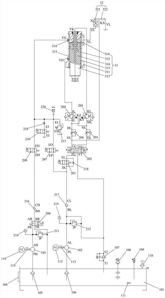
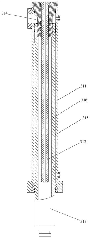
The invention relates to the field of tire forming, and discloses an integrated hydraulic system and a tire vulcanizing machine. The integrated hydraulic system comprises a hydraulic pump source, a control valve block and an executing mechanism, the executing mechanism comprises an integrated oil cylinder and a liquid filling unit, the integrated oil cylinder comprises a cylinder body, a static piston rod and a movable piston rod, the static piston rod is fixedly arranged in the cylinder body, the movable piston rod is arranged in the cylinder body in a sliding mode and matched with the static piston rod in a sliding mode, a rodless cavity and a rod cavity are formed between the movable piston rod and the cylinder body, a fast forward cavity is formed between the movable piston rod and the static piston rod, the liquid filling unit is used for supplying hydraulic oil to the rodless cavity, and the hydraulic pump source supplies the hydraulic oil to the rod cavity, the rodless cavity and the fast forward cavity through a control valve block. The system is compact in structure, reduces the occupied space, is simple and convenient to install, improves the working efficiency, provided with few pipeline connecting points, is low in leakage probability of the hydraulic oil, realizes quick die assembly without additionally outputting flow by an oil pump, reduces the cost and energy consumption, and reduces noise.

Description

technical field [0001] The invention relates to the field of tire building, in particular to an integrated hydraulic system and a tire curing machine. Background technique [0002] The hydraulic vulcanizer is the equipment used in the vulcanization process in the tire production process, and it is one of the key equipment that determines the quality of the tire. In the existing hydraulic vulcanizing machine, the actions of opening and closing the mold, increasing the clamping force, lifting and lowering of the central mechanism, expanding and contracting the movable mold, and lifting and lowering the tire loading mechanism are all realized by hydraulic transmission, which has fast response speed, reliable action and high efficiency, and can realize Stepless speed regulation, good performance, greatly reducing user operating costs and improving equipment utilization. [0003] The existing hydraulic vulcanizers have the following disadvantages: the mold opening and closing cy...

Claims


Application Information

Patent Timeline
Patent Type & Authority Applications(China)
IPC IPC(8): F15B21/08F15B11/17F15B13/06F15B15/14F15B3/00B29C33/24B29C33/20B29C35/02B29L30/00
CPCF15B21/087F15B11/17F15B13/06F15B15/1423F15B15/149F15B3/00B29C33/24B29C33/20B29C35/02B29L2030/00
Inventor 索欢欢
Owner SAFE RUN & HISCENT MACHINERY SUZHOU
Learn More