Photoetching machine motion table system

A motion table and lithography machine technology, applied in the field of lithography machines, can solve the problems of surrounding air disturbance, influence, local pressure fluctuation can not be ignored, etc., to achieve the effect of ensuring stable operation and avoiding the expansion of airflow

Pending Publication Date: 2021-07-27
上海图双精密装备有限公司
View PDF0 Cites 1 Cited by
  • Summary
  • Abstract
  • Description
  • Claims
  • Application Information

AI Technical Summary

Problems solved by technology

[0004] The purpose of the present invention is to provide a lithography machine moving table system to solve the problem that the moving table in the prior art will cause airflow disturbances in the surrounding air when the moving table is moving, and the local pressure fluctuations caused by the airflow disturbances under high-speed movement cannot be ignored. The problem that makes the high-precision sensors and measurement components near the motion platform susceptible to disturbance forces

Method used


Image

  • Photoetching machine motion table system
  • Photoetching machine motion table system
  • Photoetching machine motion table system

Examples


Embodiment 1

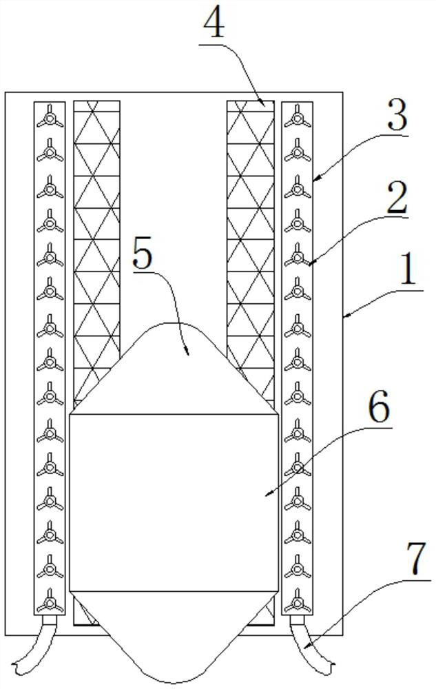
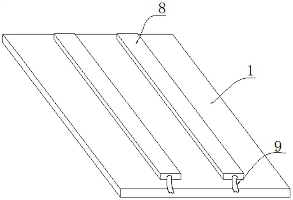
[0025] see figure 1 As shown, in the embodiment of the present invention, a lithography machine moving table system includes a base 1 and a moving table 6 above the base 1, and the moving table 6 can move above the base 1;

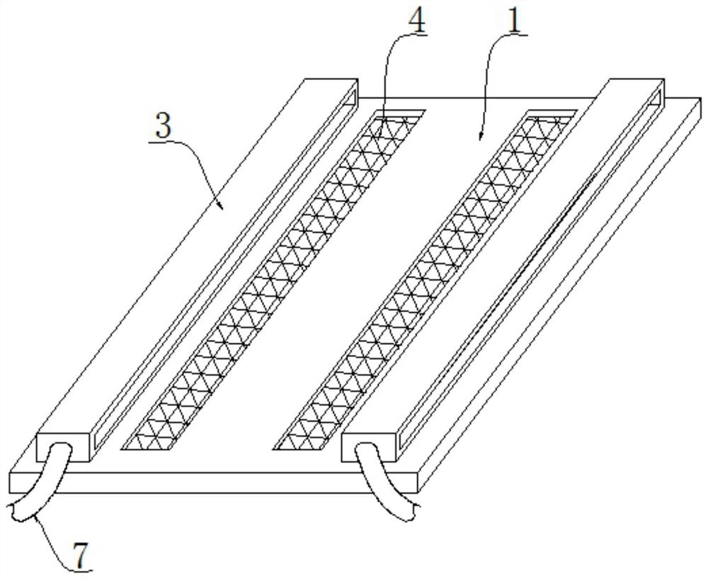
[0026] combine figure 1 and figure 2 As shown, both sides of the upper surface of the base 1 are equipped with anti-expansion cover 3, and the anti-expansion cover 3 is a ventilation structure on both sides. external transmission;

[0027] combine figure 1 and Figure 4 As shown, the inside of the anti-expansion cover 3 is equipped with side-by-side wind collection assemblies 2, the wind collection assembly 2 includes a central shaft 21 fixed inside the anti-expansion cover 3, and the circumference of the central shaft 21 is installed with a mounting cylinder 24 for rotation. The outside of 24 is uniformly equipped with fan blades 23. When the air flow passes through the anti-expansion cover 3, it will push the fan blades 23, so that the fan blades 3...

Embodiment 2

[0036] see figure 1 As shown, in the embodiment of the present invention, a lithography machine moving table system includes a base 1 and a moving table 6 above the base 1, and the moving table 6 can move above the base 1;

[0037] combine figure 1 and figure 2 As shown, both sides of the upper surface of the base 1 are equipped with anti-expansion cover 3, and the anti-expansion cover 3 is a ventilation structure on both sides. external transmission;

[0038] combine figure 1 and Figure 4 As shown, the inside of the anti-expansion cover 3 is equipped with side-by-side wind collection assemblies 2, the wind collection assembly 2 includes a central shaft 21 fixed inside the anti-expansion cover 3, and the circumference of the central shaft 21 is installed with a mounting cylinder 24 for rotation. The outside of 24 is uniformly equipped with fan blades 23. When the air flow passes through the anti-expansion cover 3, it will push the fan blades 23, so that the fan blades 3...


PUM


Abstract

The invention discloses a photoetching machine motion table system which comprises a base and a motion table located above the base. Anti-expansion covers are installed at the two sides of the upper surface of the base, each anti-expansion cover is of a two-side ventilation structure, and side-by-side air collecting assemblies are installed in the anti-expansion covers. Each air collecting assembly comprises a middle shaft fixed in the corresponding anti-expansion cover, a mounting cylinder is rotationally installed outside the circumference of the middle shaft, and fan blades are uniformly mounted outside the mounting cylinder. According to the present invention, by arranging the air collecting assemblies, the fan blades can be pushed by the airflow generated in the movement process of the movement table, so that the fan blades and the mounting cylinder can rotate, the airflow can be consumed, and the situation that the airflow expansion influences the operation of an external sensor, can be avoided. According to the present invention, a hollow-out part is arranged on the base, part of airflow can overflow out of the hollow-out part, the situation that the airflow affects the operation of the base and the sensor on the motion table is further avoided; by arranging the vibration reduction rubber, the stable operation of the motion table is guaranteed.

Description

technical field [0001] The invention relates to the technical field of lithography machines, in particular to a motion table system of a lithography machine. Background technique [0002] In the process of semiconductor lithography, measuring and optimizing the overlay accuracy of products is very important to ensure product quality stability and improve product yield. In the integrated circuit manufacturing process, the overlay accuracy between different layers of the integrated circuit board has a great influence on the final product yield. Therefore, it is necessary to match the overlay accuracy between different exposure stations. [0003] The vertical space of the moving table in the lithography machine is narrow. When the moving table is moving, it will cause airflow disturbance in the surrounding air, and the local pressure fluctuation caused by the airflow disturbance under high-speed movement cannot be ignored, which will make the high-precision near the moving tab...

Claims


Application Information

Patent Timeline
Patent Type & Authority Applications(China)
IPC IPC(8): G03F7/20
CPCG03F7/70716G03F7/7085G03F7/70858G03F7/709
Inventor 张俊杰
Owner 上海图双精密装备有限公司
Why Eureka
Try Eureka