
Flue partition mixer

A mixer and flue technology, applied in separation methods, dispersed particle separation, chemical instruments and methods, etc., can solve the problems of long response time, no mixing measures, long measurement cycle, etc., to reduce investment costs and reduce measurement. The number of points, the effect of improving the quality of control

Pending Publication Date: 2021-07-30
XIAN TPRI BOILER ENVIRONMENTAL PROTECTION ENG CO LTD
View PDF0 Cites 0 Cited by
  • Summary
  • Abstract
  • Description
  • Claims
  • Application Information

AI Technical Summary

Problems solved by technology

[0003] 1. The distribution of NOx at the SCR inlet will often have a large deviation due to the difference in combustion conditions under different working conditions, and the distribution law will also be unstable
[0004] 2. After the opening of each manual control valve of the ammonia injection grid is optimized and adjusted for ammonia injection under a certain working condition, the amount of reductant injected into each zone is fixed. When the NOx distribution at the inlet changes greatly, the reductant and NOx mixing will be difficult to meet the requirements;
[0005] 3. With the promulgation and implementation of ultra-low emission environmental protection regulations, conventional SCR is more sensitive to the deviation of inlet NOx distribution, which is more likely to cause local excess ammonia to escape, and threaten the safe and reliable operation of subsequent equipment
[0006] The traditional partitioned dynamic ammonia injection technology is to arrange a large number of flue gas component measuring points at the SCR outlet, and change the manual valve of the ammonia injection grille to an automatic regulating valve. The disadvantage of this method is that there is no mixing measure with a large cross-section The large number of partitions leads to a large number of flue gas composition measuring points and regulating valves. Not only is the investment cost high, but the measurement cycle is long, the response time is long, and the adjustment quality is poor. Therefore, it is necessary to design a new type of flue gas mixer and method. , to achieve uniform mixing of components in the flue gas, while reducing investment costs, while reducing the number of partitions

Method used


Image

  • Flue partition mixer
  • Flue partition mixer
  • Flue partition mixer

Examples


Embodiment Construction

[0020] The present invention is described in further detail below in conjunction with accompanying drawing:

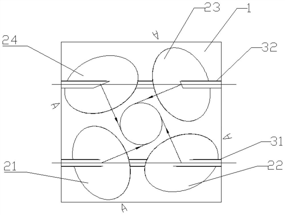
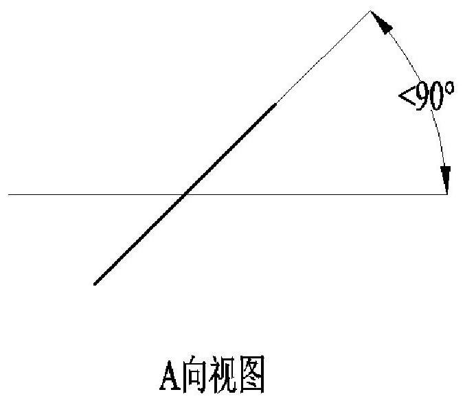
[0021] refer to figure 1 and figure 2 , the flue partition mixer according to the present invention, the cross section of the flue is divided into several partitions 1, wherein, each partition 1 is provided with a deflector vane group, wherein the deflector blades in the deflector vane group deflect along the same rotation direction The centerlines of each deflecting vane in the deflecting vane group are tangent to the same circle, and the rotation deflection direction of each deflecting blade in the deflecting blade group in the adjacent partition 1 is opposite; the deflecting blade group includes the first deflecting blade 21, the second Two deflector vanes 22 , a third deflector vane 23 and a fourth deflector vane 24 .

[0022] The present invention also includes a first fixing rod 31 for fixing the first deflecting vane 21 and the second deflecting vane 22 and a...


PUM


Abstract

The invention discloses a flue partition mixer. The cross section of a flue is divided into a plurality of partitions; each partition is internally provided with a bias flow blade group; bias flow blades in the bias flow blade groups deflect along the same rotation direction; the center lines of the bias flow blades in the bias flow blade groups are tangent to the same circle; the rotating deflection directions of all the bias flow blades in the bias flow blade groups in the adjacent partitions are opposite; the mixer can achieve uniform mixing of smoke in all the partitions; and the number of the partitions is small, so that the investment cost is low.

Description

technical field [0001] The invention belongs to the field of flue gas mixing treatment, and relates to a flue partition mixer. Background technique [0002] Flue gas mixing is an important step to improve flue gas treatment, especially in the SCR system. The existing ammonia injection and mixing technology of the conventional SCR system adopts the installation of ammonia injection in the entire flue section, which can manually adjust the amount of ammonia sprayed in each zone. grille, and then use a static mixer to promote the mixing of ammonia and flue gas. This method requires that the NOx distribution at the SCR inlet is relatively uniform and stable, and the opening of each manual control valve is adjusted according to the NOx distribution at the SCR inlet to control the amount of reducing agent injected into each zone. The downside of this approach is that. [0003] 1. The NOx distribution at the SCR inlet often has a large deviation due to the difference in combustio...

Claims


Application Information

Patent Timeline
Patent Type & Authority Applications(China)
IPC IPC(8): B01D53/86
CPCB01D53/8631
Inventor 安振黄钢英尚桐杨晓刚石磊周梦伟姚皓罗志董陈贾林权常磊王晓冰牛国平
Owner XIAN TPRI BOILER ENVIRONMENTAL PROTECTION ENG CO LTD
Learn More