Supercharge Your Innovation With Domain-Expert AI Agents!

Workpiece swing and offset detection system

A detection system and offset technology, applied in measuring devices, instruments, spray devices, etc., can solve problems such as failure to achieve timeliness, product quality impact, and unfavorable spray gun swing amplitude exceeding the standard fault.

Active Publication Date: 2021-07-30
上海鼎湖自动化系统有限公司
View PDF8 Cites 0 Cited by
  • Summary
  • Abstract
  • Description
  • Claims
  • Application Information

AI Technical Summary

Problems solved by technology

[0004] In order to overcome the existing technology, the spraying robot does not have a system that can effectively monitor the swing range of the spray gun, and artificially judge whether the swing range of the spray gun is lower than the limit value or higher than the limit value according to the spraying quality of the sprayed product, which cannot achieve timeliness. The over-value phenomenon of the swing amount of the spray gun cannot be found at the first time, which will affect the quality of the product after spraying, and is not conducive to the short-term discharge of the drawbacks of the swing range of the spray gun exceeding the standard fault. A set of laser rangefinders are respectively installed on the extended gun frame of the arm, and the two sets of laser rangefinders are respectively installed on the inner side of the housing with a cylinder control movable door. In the application, under the joint action of relevant mechanisms and software units, the Detect the distance between the nozzle of the spray gun and the workpiece to be sprayed. When the distance is too large, a warning message can be issued according to the specific situation, so that the technician can know the distance between the workpiece and the nozzle of the spray gun. phenomenon, and make targeted adjustments, thereby ensuring the workpiece swing and offset detection system for the workpiece spraying effect

Method used


Image

  • Workpiece swing and offset detection system
  • Workpiece swing and offset detection system

Examples


Embodiment Construction

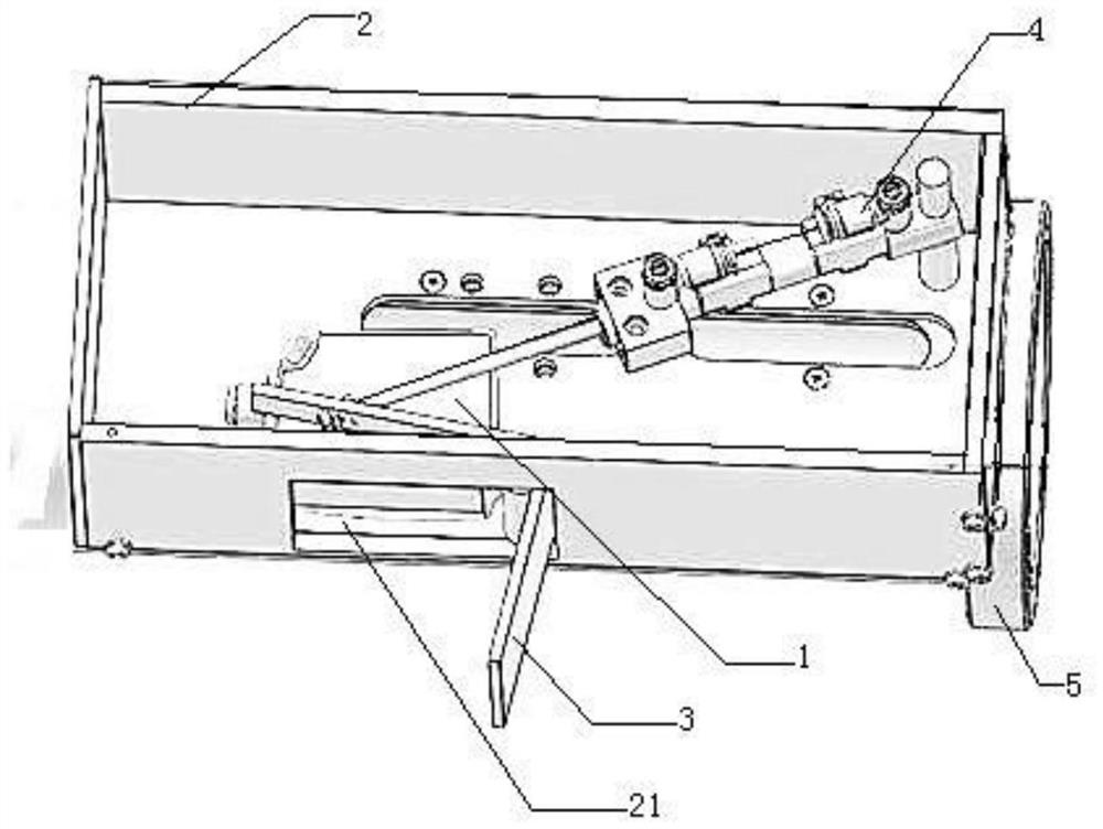
[0016] figure 1 , 2 As shown in , the workpiece swing and offset detection system includes a laser rangefinder 1, a housing 2, a movable door 3, a cylinder 4, a PLC (not shown in the figure), and an industrial computer (not shown in the figure); There are two sets of laser rangefinder 1, shell 2, "┑" type movable door 3, and cylinder 4 respectively. The front left part of the casing 2 has a rectangular opening 21, and the height of the front end of the movable door 3 is lower than that of the rear end. The middle part of movable plate 3 is rotated and installed in the front part of the housing 2 at the right side of the opening 21, and the laser range finder 1 is installed in the left front end of the housing, and its detection head is located at the rear end of the opening 21, behind the dodge door 3. The end is located on the upper part of the laser rangefinder 1, the right end of the cylinder body of the cylinder 4 is rotated and installed on the right end of the housing 2...


PUM


Abstract

A workpiece swing and offset detection system comprises laser distance meters, shells, movable doors, air cylinders, a PLC, and an industrial personal computer. Opening are formed in the front ends of the shells, the middles of movable plates are rotationally mounted at side ends of the openings, the laser distance meters are mounted in certain sides of the shells, barrels of the air cylinders are rotationally mounted in the other sides of the shells, piston rods of the air cylinders and the rear ends of the movable doors are mounted together in a hinged manner, and the shells are mounted on extension gun racks of spray-coating robots. Application software including a workpiece data unit, a data acquisition unit, a data threshold library unit, a comparison unit, and an alarm unit are installed in the industrial personal computer. The system can be used for detecting interval offsets between a gun head of a spray gun and a workpiece in the X-axis direction and the Y-axis direction. If an interval is appropriate, a PLC directly controls the spray gun to perform a spray-coating operation. The spray gun moves to approach the workpiece, and when the interval finally does not meet a requirement, the alarm unit can remind a technician of maintenance in time, and a spray-coating effect of the workpiece is effectively ensured.

Description

technical field [0001] The invention relates to the technical field of spraying robot matching, in particular to a workpiece swing and offset detection system. Background technique [0002] With the development of industrial technology, more and more intelligent robots are used in the production field. For example, the spraying robot used in the field of automobile production is one of them. When the spraying robot is working, controlled by its own PLC programming, the robot arm drives the spray gun and its gun head to move along a certain trajectory according to the programming, and then sprays the surface of the workpiece. In reality, due to various factors such as the quality of the spray gun itself, after the PLC controls the robot arm to drive the spray gun to the spraying station, the gun head of the spray gun may swing in the X-axis or Y-axis direction (the mass of the robot arm may also The problem causes the spray gun to swing), which in turn causes the offset (spa...

Claims


Application Information

Patent Timeline
Patent Type & Authority Applications(China)
IPC IPC(8): B05B12/12B05B13/04G01B11/02G01B11/14
CPCB05B12/124B05B13/0431G01B11/02G01B11/14
Inventor 王磊符传明
Owner 上海鼎湖自动化系统有限公司
Features
  • R&D
  • Intellectual Property
  • Life Sciences
  • Materials
  • Tech Scout
  • Unparalleled Data Quality
  • Higher Quality Content
  • 60% Fewer Hallucinations
Learn More