Flue gas desulfurization method of heating boiler and device thereof

A technology for heating boilers and desulfurization devices, applied in separation methods, chemical instruments and methods, lighting and heating equipment, etc., can solve problems such as on-site dust pollution, incomplete dehydration, and decreased desulfurization efficiency, to ensure spraying effect and desulfurization The effect of stable product and no dust pollution

Inactive Publication Date: 2010-08-18
TIANJIN XIAOWO ENVIRONMENTAL PROTECTION ENG CO LTD
View PDF8 Cites 7 Cited by
  • Summary
  • Abstract
  • Description
  • Claims
  • Application Information

AI Technical Summary

Problems solved by technology

[0003] 1. Most of them are dust removal and desulfurization integrated devices, and most of them are water film or water bath desulfurization dust collectors. The desulfurization effect is poor, and the dust removal ash is mixed with the desulfurization circulating fluid, which not only causes a decline in desulfurization efficiency, but also is not conducive to the treatment of by-products
[0004] 2. The existing desulfurization atomization nozzle adopts the form of a shower head, which is easy to block and cannot guarantee the normal operation of the atomization device
[0005] 3. The problem of water in the exhaust gas is serious
Most of the traditional dehydration and defogging devices adopt steel ball net structure, which is easy to be blocked by smoke and dust, resulting in large resistance, incomplete dehydration, easy to corrode the subsequent flue, and acid mist to pollute the external environment
[0006] 4. There is no oxygen aeration device, resulting in unstable desulfurization products and easy to cause secondary pollution
In the traditional desulfurization process, the final product is SO 3 2- Compounds, easy to precipitate SO in wind, rain and sun exposure 2 or form H 2 SO 3 , re-enter the air or flow into the sewer to cause secondary pollution
[0007] 5. Severe fouling of the pipes and walls of the desulfurization system may easily cause pipeline blockage
[0008] 6. In the existing desulfurization agent (pharmaceutical) part, simple pharmaceutical methods such as manual direct dumping are mostly used, which not only causes dust pollution on site, but also has high labor intensity for workers, and the pulping effect is very poor, prone to precipitation, waste of resources, etc.

Method used


Image

  • Flue gas desulfurization method of heating boiler and device thereof
  • Flue gas desulfurization method of heating boiler and device thereof

Examples


Embodiment 1

[0038] A heating boiler flue gas desulfurization method, comprising the following process:

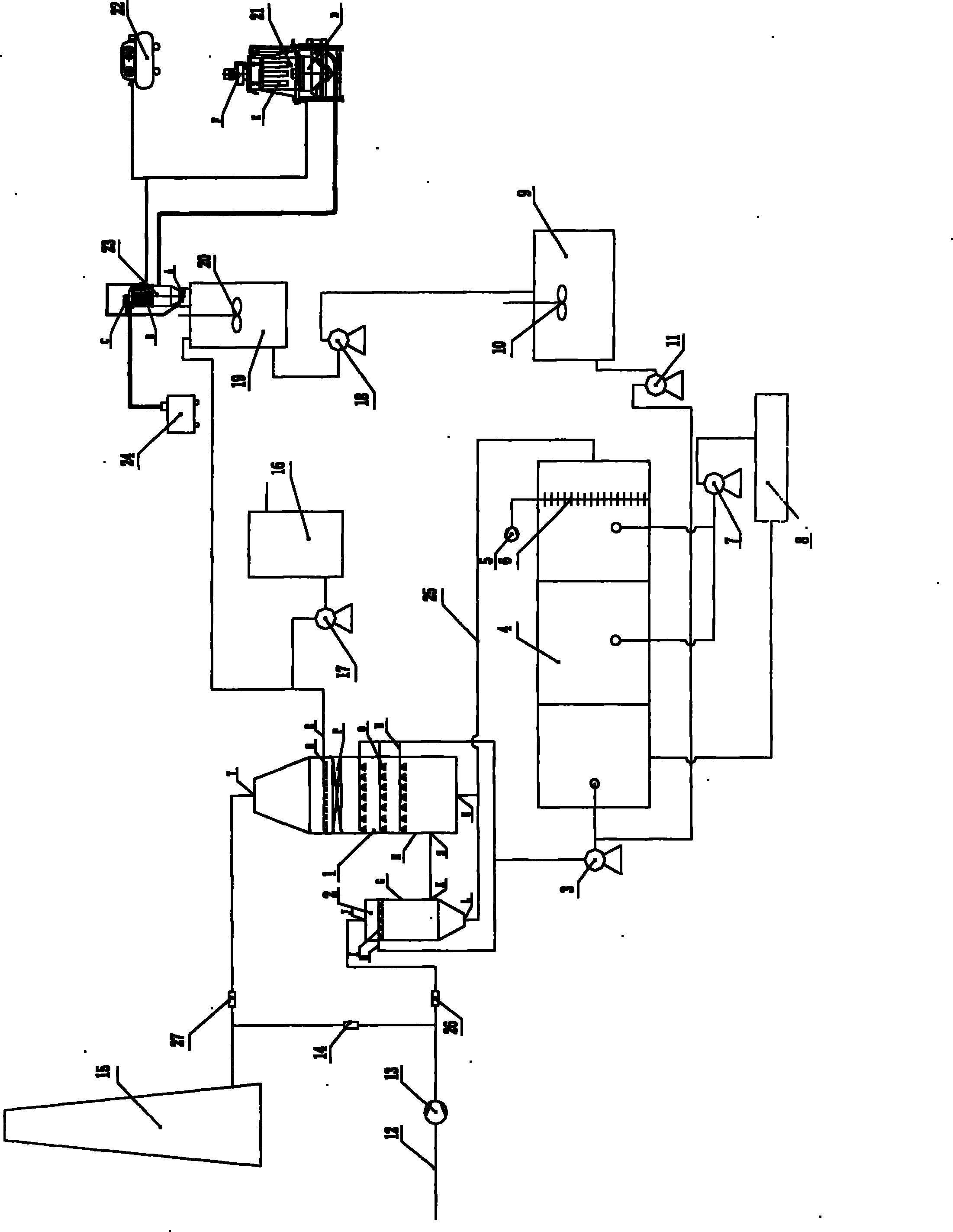
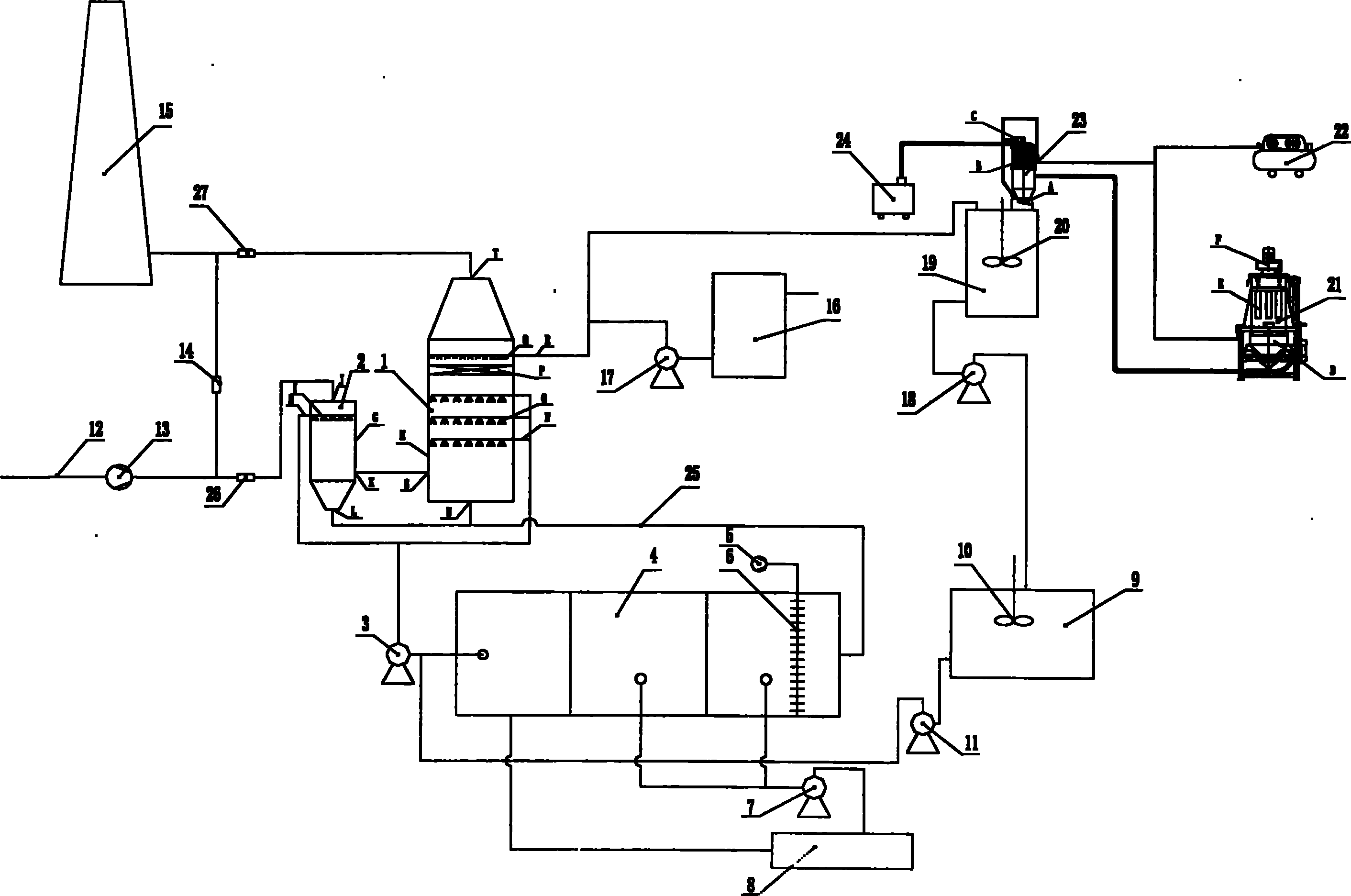
[0039] Pre-cooling: The flue gas after dust removal is sent to the pre-cooling tower 2 by the induced draft fan 13 through the flue inlet 12 for pre-cooling; the absorption liquid is atomized and sprayed to the pre-cooling tower 2 through the circulation pump 3;

[0040] Desulfurization: the pre-cooled flue gas enters the desulfurization tower 1 for desulfurization; the absorption liquid is atomized and sprayed to the desulfurization tower 1 through the circulation pump 3; the desulfurized flue gas is discharged through the chimney 15;

[0041] Magnesium oxide pulping: Magnesium oxide powder is pulped in the digestion tank 19, and the slurry is sent to the circulation pump 3 through the slurry pump 11, and atomized and sprayed in the flue gas precooling tower 2 and the desulfurization tower 1;

[0042] Aeration of the absorption liquid: the blower 5 aerates the absorption liquid in the...

Embodiment 2

[0047] A flue gas desulfurization device for heating boilers, the flue gas after dust removal treatment enters the flue 12 through the induced draft fan 13 to connect to the precooling tower 2, the precooling tower connects to the desulfurization tower 1 through the flue, and the desulfurization tower 1 connects to the flue gas discharge The chimney 15; the precooling tower 2 and the desulfurization tower 1 have an absorption liquid atomization injection mechanism; The absorption liquid circulation pool 4 is connected to the pre-cooling tower 2 and the desulfurization tower 1, the atomization jet circulation pump 3; the blower 5 is connected to the aeration distribution pipe 6 in the circulation pool 4; the circulation pool 4 is connected to the slurry discharge pump 7 and is connected to the magnesium sulfate crystal dehydrator 8. The dehydrator 8 has a passage for the extracted water to flow into the circulating pool 4; the jet circulation pump 3 is connected to the digester ...


PUM


Abstract

The invention relates to a flue gas desulfurization method of a heating boiler and a device thereof, belonging to the technical field of heating boilers. The flue gas desulfurization method of the heating boiler comprises the following steps of: precooling, desulfurizing, magnesium oxide pulping, absorption liquid aeration and crystallizing dehydration. In the precooling step, glue gas enters a precooling tower through a flue gas inlet channel for precooling, and absorption liquid is atomized and sprayed; in the desulfurizing step, the flue gas enters a desulfurizing tower for desulfurizing, and the absorption liquid is atomized and sprayed; the flue gas is discharged through a chimney; in the step of magnesium oxide pulping, magnesium oxide powder is pulped in a digestion tank; in the step of absorption liquid aeration, an air blower carries out aeration on the absorption liquid by a gas distribution pipe; and in the step of crystallizing dehydration, magnesium sulfate crystal size is crystallized and dehydrated. The flue gas desulfurization device of the heating boiler is characterized in that the flue gas inlet channel is communicated with the precooling tower by a draught fan; the precooling tower is communicated with the desulfurizing tower through a flue; the desulfurizing tower is communicated with the chimney; an absorption liquid atomization spray mechanism is respectively arranged in the precooling tower and the desulfurizing tower; the air blower is communicated with an aeration gas distribution pipe; a circulating water pool is communicated with a dehydrator; and a spray circulating pump is communicated with the digestion tank. The invention has the advantages of good desulfurizing effect, high desulfurizing efficiency, little water along with flue gas discharge, convenient operation, environmental protection and the like.

Description

technical field [0001] The invention belongs to the technical field of heating boilers, and in particular relates to a flue gas desulfurization method of a heating boiler and a device thereof. Background technique [0002] At present, the flue gas desulfurization of industrial heating boilers, especially the wet desulfurization process, has the following shortcomings in specific applications: [0003] 1. Most of them are dust removal and desulfurization integrated devices, and most of them are water film or water bath desulfurization dust collectors. The desulfurization effect is poor, and the dust removal ash is mixed with the desulfurization circulating fluid, which not only causes a decline in desulfurization efficiency, but also is not conducive to the treatment of by-products . [0004] 2. The existing desulfurization atomizing nozzle is in the form of a shower head, which is easy to block and cannot guarantee the normal operation of the atomizing device. [0005] 3. ...

Claims


Application Information

Patent Timeline
Patent Type & Authority Applications(China)
IPC IPC(8): B01D53/78B01D53/50C01F7/40F23J15/04
Inventor 钱松飞孙雷宇赵纪柱
Owner TIANJIN XIAOWO ENVIRONMENTAL PROTECTION ENG CO LTD
Why Eureka
Try Eureka