Precise electrolytic machining process for multi-tooth turbine blade

A turbine blade and processing technology, which is applied in the field of precision electrolytic machining of multi-tooth turbine blades, can solve problems such as restricting the processing efficiency of turbine blades and reducing processing stability.

Active Publication Date: 2021-07-30
JIANGSU JIANGHANGZHI AIRCRAFT ENGINE COMPONENTS RES INST CO LTD
View PDF7 Cites 2 Cited by
  • Summary
  • Abstract
  • Description
  • Claims
  • Application Information

AI Technical Summary

Problems solved by technology

In practice, the higher the processing voltage, the higher the electrolysis efficiency. However, due to the large amount of heat generated in the processing gap and the formation of a large number of products, the processing

Method used


Image

  • Precise electrolytic machining process for multi-tooth turbine blade
  • Precise electrolytic machining process for multi-tooth turbine blade
  • Precise electrolytic machining process for multi-tooth turbine blade

Examples


Embodiment Construction

[0036] In order to make the technical means, creative features, goals and effects achieved by the present invention easy to understand, the present invention will be further described below in conjunction with specific embodiments.

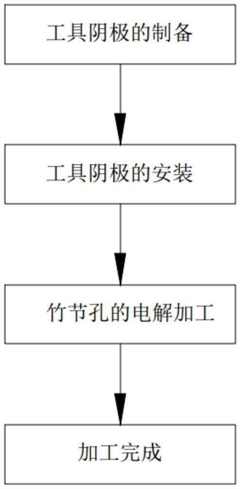
[0037] Such as Figure 1 to Figure 8 As shown, the present invention discloses a multi-tooth turbine blade precision electrolytic machining process, which specifically includes the following steps:

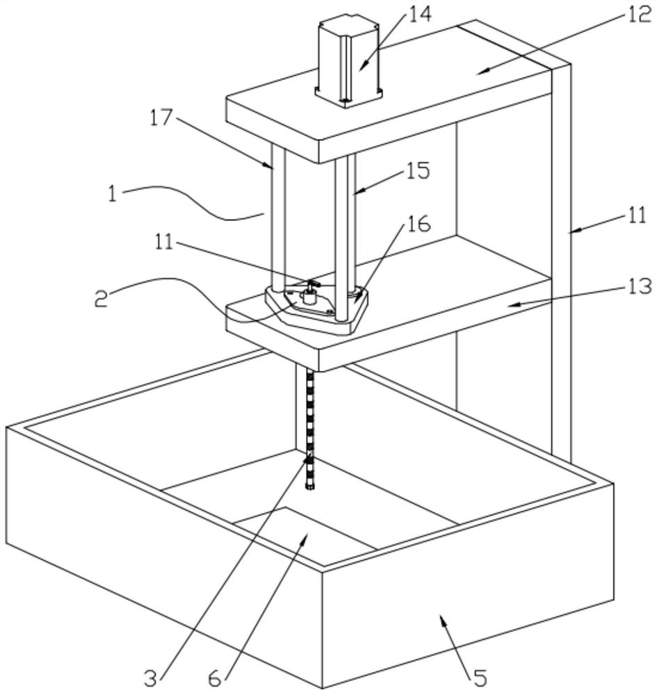
[0038] Step 1, prepare the tool cathode 3 by electrolytic copying method, and install the support ring 4 at the lower end of the tool cathode 3;

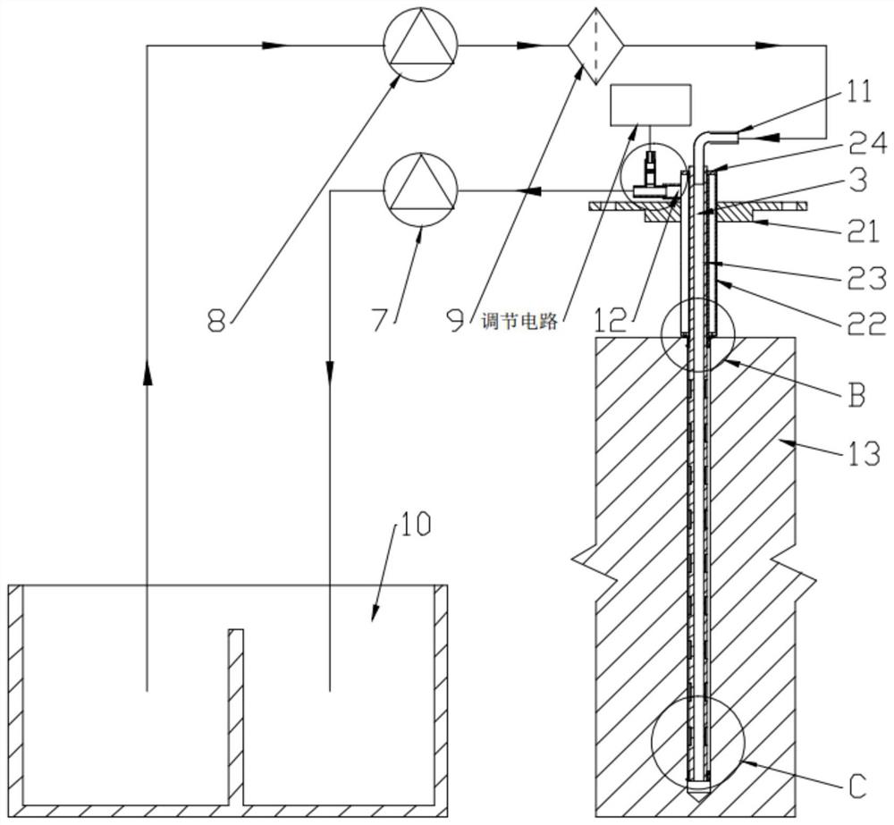
[0039] Step 2. Connect the upper end of the tool cathode 3 to the positioning tool 2, then install the positioning tool 2 into the lifting mechanism 1, connect the tool cathode 3 to the negative pole of the power supply, and install a liquid inlet pipe 11 at the entrance of the tool cathode 3, and complete For the installation of the tool cathode 3, the return pipe 12 provided on the side of the positionin...


PUM


Abstract

The invention discloses a precise electrolytic machining process for a multi-tooth turbine blade, and relates to the technical field of electrolytic machining for turbine blades. The precise electrolytic machining process for the multi-tooth turbine blade comprises the steps of preparation for a tool cathode, installation for the tool cathode, electrolytic machining for a bamboo joint hole and the like. According to the invention, the defects of a traditional method are overcome, and under the condition of high voltage, the stability of the machining process can still be guaranteed, so that the electrolytic machining efficiency is increased, and the machining time is shortened; and when the temperature of an electrolyte rises, the flow speed of the electrolyte can be adjusted through an adjusting module so as to accelerate heat dissipation of an electrolytic machining area, so that stable control over the temperature of the electrolyte is achieved.

Description

technical field [0001] The invention belongs to the technical field of electrolytic machining of turbine blades, and in particular relates to a precision electrolytic machining process for multi-tooth turbine blades. Background technique [0002] With the development of the aviation industry, the temperature of the turbine inlet is getting higher and higher, so higher requirements are put forward for the heat resistance of the blade material. At present, the cooling of the blade mainly adopts the circulation channels of different shapes inside the blade ( That is, the cooling channel) to increase the heat dissipation of the blade. As a high-efficiency and low-resistance blade cooling form, the ribbed cooling channel can be applied on the leading edge, blade pot, and blade back of the turbine blade. hole". During the heat transfer process of the "bamboo hole", the ribs on the side wall of the cooling hole have a greater disturbance to the fluid. This disturbance destroys the...

Claims


Application Information

Patent Timeline
IPC IPC(8): B23H3/00B23H3/04B23H3/08
CPCB23H3/00B23H3/04B23H3/08
Inventor 吴江严小琳曹春晓
Owner JIANGSU JIANGHANGZHI AIRCRAFT ENGINE COMPONENTS RES INST CO LTD
Why Eureka
Try Eureka