
Intelligent assembly device for clamp spring and rotary shaft
An assembly device and shaft technology, applied in the direction of assembly machines, metal processing, metal processing equipment, etc., can solve the problems of low circlip assembly efficiency, unrealized automatic operation, and reduced circlip assembly efficiency, etc.
Patent Information
- Authority / Receiving Office
- CN · China
- Current Assignee / Owner
- Publication Date
- 2021-07-30
Smart Images
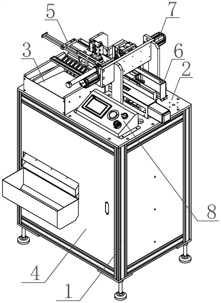
Figure 1 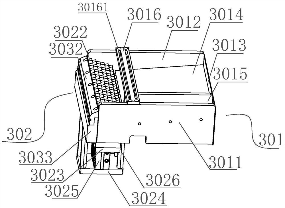
Figure 2 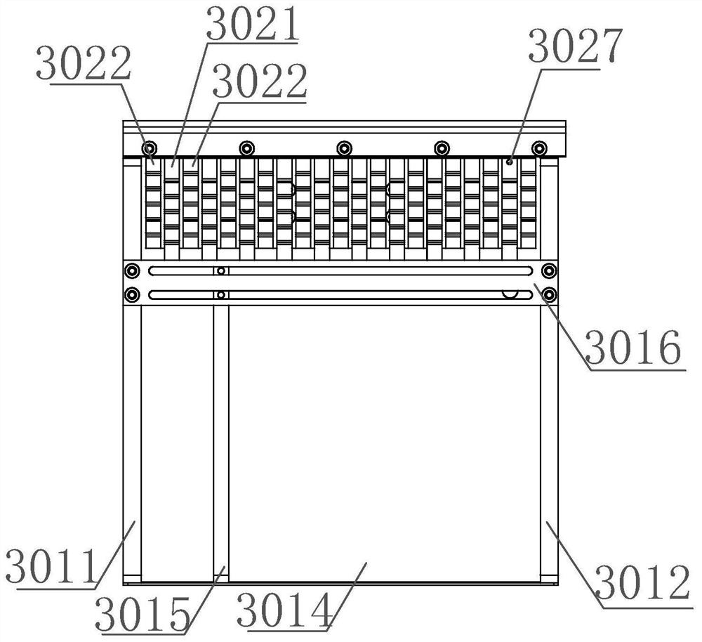
Figure 3
Abstract
Description
Technical field
[0001] The present invention relates to the field of mechanical assembly technology, and in particular, a hawfrings and a shaft intelligent assembly device. Background technique
[0002] In the field of production and assembly technology in mechanical products, often involve assembly of the intercalasts, the interplament is typically mounted in the plug-in groove of the machine shaft, and the effect of preventing axial axial movement, the torch is not in place, often affecting the entire The quality of the mechanical product, and there is a safety hazard. In the prior art, it is generally used to use the caliper to complete the cartridge of the cartridge. This mode is low, the labor intensity is high, the production cost is higher, and in the process of assembly Because the manual operation is not in place, it is easy to cause a good product rate or excessive force to cause personal injury.
[0003] In the case where the industry competition is increasing, it has ...
Examples
Embodiment Construction
[0045] The present invention will be described below with reference to the accompanying drawings and examples.
[0046] like figure 1 As shown, a ring spring and a rotating shaft intelligent assembly device includes a support frame 1, a table panel 2, a rotating shaft feeding device 3, a shaft limit device 5, a reed device 6, a housing spring assembly device 7, and control The table panel 2 is fixed to the support frame 1, the rotating shaft chargeding device 3, the rotating shaft limit device 5, the reed device 6, and the box assembly device 7 are connected to the table panel 2 and Controlled by controller, respectively.
[0047] like Figure 2 - Figure 7 As shown, the rotating shaft feeding device 3 includes a shaft storage cartridge 301, a shaft sorting material 302, a rotating shaft tank 303, a rotor recovery mechanism 304, and a blank drive mechanism 305, the rotating shaft storage. The cartridge 301, the shaft sorting material 302, the rotating shaft tank 303 is arranged in t...