Robot grinding system and grinding clamp thereof

A robot and fixture technology, applied in the field of grinding, can solve the problems of waiting for the assembly line to stop and affect the grinding efficiency, and achieve the effect of improving the replacement speed, improving efficiency and economic benefits.

Pending Publication Date: 2021-07-30
安徽精翔自动化科技有限公司
View PDF0 Cites 5 Cited by
  • Summary
  • Abstract
  • Description
  • Claims
  • Application Information

AI Technical Summary

Problems solved by technology

[0004] The purpose of the present invention is to solve the problem that the manual replacement of the grinding wheel in the prior art will cause the economic loss of the assembly line and affect the grinding efficiency, and propose a robot grinding system and its grinding fixture

Method used


Image

  • Robot grinding system and grinding clamp thereof
  • Robot grinding system and grinding clamp thereof
  • Robot grinding system and grinding clamp thereof

Examples


Embodiment 1

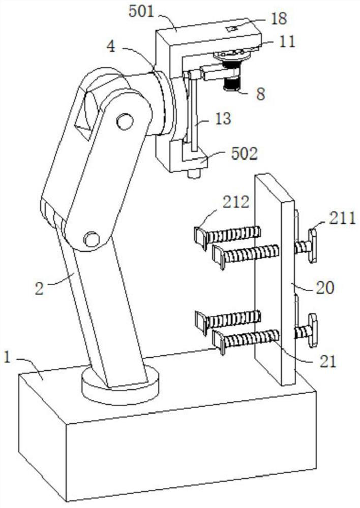
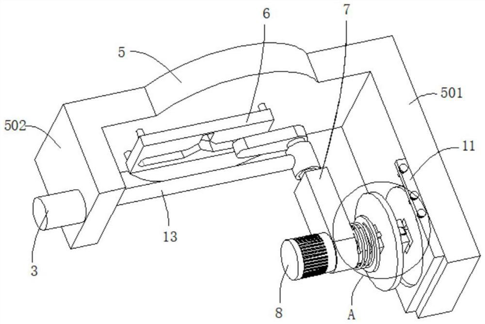
[0034] refer to Figure 1-7, a robot grinding system, comprising a grinding table 1, the top of the grinding table 1 is connected with a mechanical arm 2 and a grinding fixture, the end of the mechanical arm 2 away from the grinding table 1 is connected with a rotating plate 4, and the outer wall of the rotating plate 4 is connected with a working plate 5 The two sides of the outer wall of the working plate 5 are respectively connected with the first side plate 501 and the second side plate 502, the outer wall of the working plate 5 is connected with the stroke plate 6 through the connecting rod, the outer wall of the stroke plate 6 is dug with a track groove 601, and the inner wall of the track groove 601 A moving rod 602 is movably connected, the outer wall of the moving rod 602 is connected with a connecting plate 603, the outer wall of the connecting plate 603 is connected with a fixed rod 604, and the end of the fixed rod 604 away from the connecting plate 603 is connected...

Embodiment 2

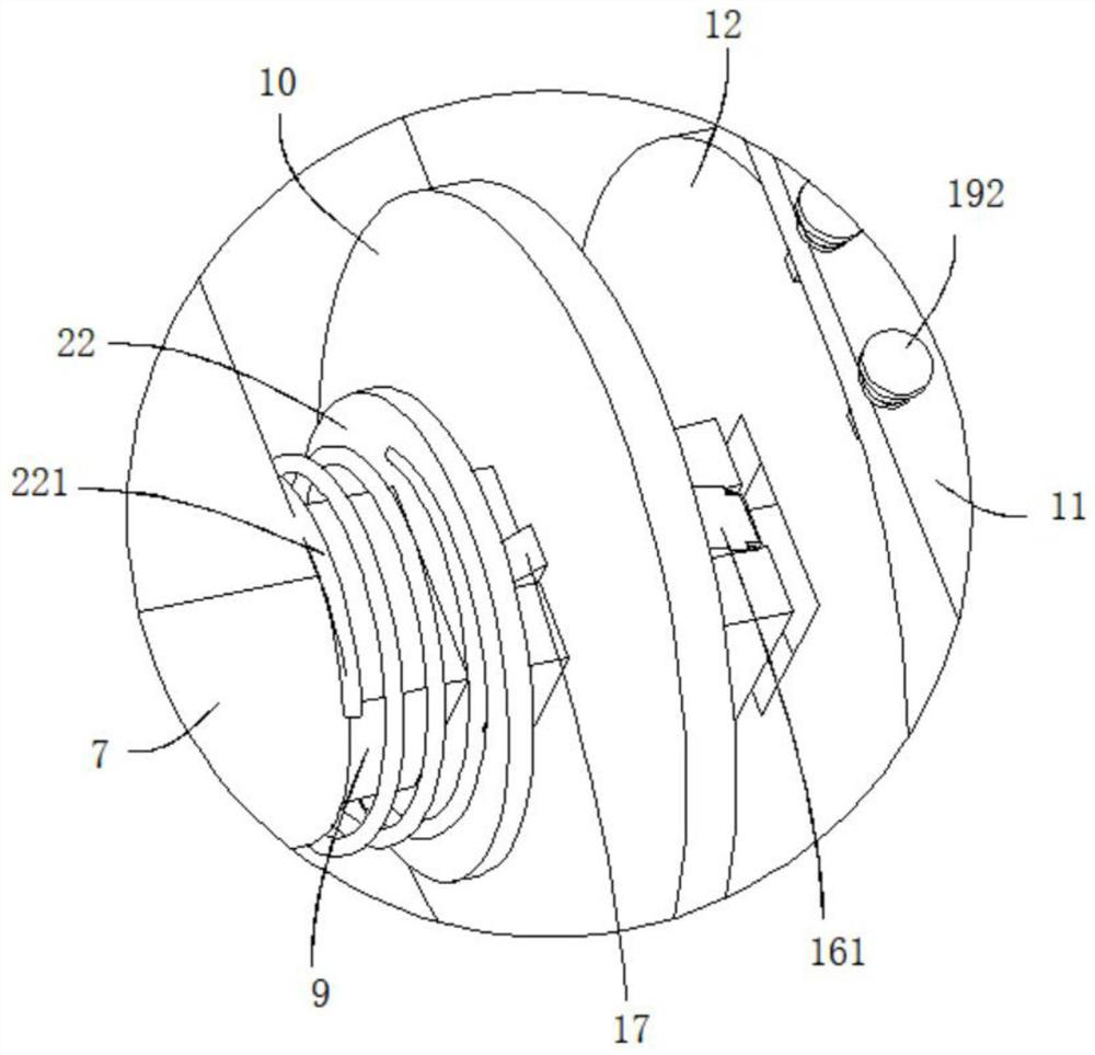
[0044] refer to image 3 , Figure 6 and Figure 8 , a robot grinding system, which is basically the same as that of Embodiment 1, furthermore, the outer wall of the rotating seat 9 is slidably connected with a baffle plate 22, and the outer wall of the rotating seat 9 is sleeved with a third elastic element 221, and the two ends of the third elastic element 221 The ends are respectively connected with the fixed seat 7 and the baffle plate 22; the working grinding wheel 10 is squeezed by the spare grinding wheel 12, so that the working grinding wheel 10 is placed between the block 17 and the baffle plate 22, and the working grinding wheel 10 is limited to avoid waste of work. The emery wheel 10 shakes when grinding the workpiece, causing the equipment to vibrate and affecting the grinding effect.

[0045] Placement frame 11 both sides outer walls are all excavated with chute 19, and chute 19 inwalls are slidably connected with slide bar 191, and the outer wall of slide bar 1...


PUM


Abstract

The invention discloses a robot grinding system and a grinding clamp thereof, and belongs to the technical field of grinding. The robot grinding system comprises a grinding table, and the top of the grinding table is connected with a mechanical arm and the grinding clamp; the end, away from the grinding table, of the mechanical arm is connected with a rotating plate, and the outer wall of the rotating plate is connected with a working plate; the two sides of the outer wall of the working plate are connected with a first side plate and a second side plate separately, and the outer wall of the working plate is connected with a stroke plate through a connecting rod; a rail slot is formed in the outer wall of the stroke plate, and a movable rod is connected with the inner wall of the rail slot movably; a connecting plate is connected to the outer wall of the movable rod; a fixing rod is connected to the outer wall of the connecting plate; a fixing base is connected to one end, far away from the connecting plate, of the fixing rod; and a motor is connected to the outer wall of the fixing base. According to the robot grinding system, the replacement speed between grinding wheels can be increased, and it is ensured that normal grinding operation cannot be affected by the replacement operation of the grinding wheels; and the situation that an assembly line stops for waiting due to replacement of the grinding wheels is avoided, and the efficiency and economic benefits of a production line can be improved.

Description

technical field [0001] The invention relates to the technical field of grinding, in particular to a robot grinding system and a grinding fixture thereof. Background technique [0002] As we all know, my country is a big country in the foundry industry. In the manufacturing process of large castings (500 kg-3 tons), after doffing of large castings, mechanical cutting, oxyacetylene flame cutting, arc cutting or plasma cutting are generally used to cut the riser Remove, and then the workers will grind the surface of the casting with a hand-held grinder to make the workpiece have a smoother appearance. With the increase in labor costs and the increasing requirements of young people on the working environment, traditional manual grinding has been difficult to continue to develop, and Manual grinding has problems such as low efficiency, and it is difficult to realize automatic production, which has become a bottleneck for the further development of the grinding and polishing industr...

Claims


Application Information

Patent Timeline
Patent Type & Authority Applications(China)
IPC IPC(8): B24B41/06B24B45/00B24B27/00B25J11/00
CPCB24B27/0084B24B41/06B24B45/006B25J11/0065
Inventor 朱洪泽李翔吕飞
Owner 安徽精翔自动化科技有限公司
Why Eureka
Try Eureka