
High-airtightness air seal machine and drying processing equipment

A high-air-tight, air-closing technology, applied in lighting and heating equipment, dry solid materials, dry goods handling, etc., can solve the problems of affecting the sealing effect, easy wear and tear of the sealing device, and difficulty in production and production, and achieves purchase and use. The effect of low cost, improved work efficiency, and low price accuracy

Inactive Publication Date: 2021-07-30
MENGZHOU YUANHONG DRYING EQUIP RES & DEV CO LTD
View PDF0 Cites 0 Cited by
  • Summary
  • Abstract
  • Description
  • Claims
  • Application Information

AI Technical Summary

Problems solved by technology

There are some problems: 1. The outer circular sealing surface of such a sealing device is a circular surface or a plane, and the sealing surface of the outer circle of the sealing device is only attached to the inner wall of the valve in a small area, and the sealing effect is affected by the small sealing area.
3. Under the heavy pressure of the external force when the sealing device is adhered, the force of the sealing device at different positions is uneven. After the glue is solidified, some places of the sealing device are raised and some are sunken, resulting in the outer sealing surface of the sealing device is uneven
5. The impeller after fixing the sealing device is not machined to meet the precision requirements of cylindricity and surface profile
6. The sealing surface of the sealing ring and sealing strip is convex, which reduces the sealing area
7. The cylindricity and surface profile of the outer circular sealing surface of the sealing device fixed on the impeller do not meet the accuracy requirements, and there are different distances between the uneven sealing surface on the outer circular surface of the sealing device and the inner wall of the valve. gap, the air lock performance of the air lock is greatly reduced
[0005] The installation structure of the current air shutoff device is complex, the installation position of the guide tube on the valve body is not easy to locate, and the production is difficult
[0006] There are many problems with the air locks used in the drying processing equipment on the market. Due to the small sealing surface between the sealing device of the air lock and the inner wall of the valve, many problems of wear and tear have not been solved, resulting in the current market. The air-tightness of the air lock used in the drying processing equipment is poor, and the sealing device is easy to wear, resulting in a large amount of air leakage, which affects the drying processing efficiency of the drying processing equipment

Method used


Image

  • High-airtightness air seal machine and drying processing equipment
  • High-airtightness air seal machine and drying processing equipment
  • High-airtightness air seal machine and drying processing equipment

Examples


Embodiment 1

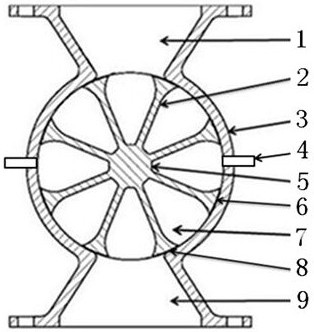
[0061] Such as figure 1 , figure 2 , image 3 A highly airtight air shutoff shown includes a valve casing, an impeller 5 , a draft tube 4 and a sealing device 8 .

[0062] The valve casing includes a valve body 3, a side cover, and a bearing. Bearing is installed in the center position of side cover, and two side covers are fixed on the both sides of valve body 3. There is a feed port 1 and a discharge port 9 on the valve housing.

[0063] The impeller 5 includes a vane 2, a baffle 11, and a transmission shaft.

[0064] The impeller 5 is inside the valve body 3 . The transmission shaft of the impeller 5 is supported by bearings on the side covers at both ends. One end of the transmission shaft is sealed in the side cover, and the other end extends out of the side cover. The transmission shaft is used to connect the power output shaft of the driving device.

[0065] The blade plate 2 and the baffle plate 11 are fixed on the transmission shaft, the blade plate 2 is fixed ...

Embodiment 2

[0092] Such as figure 1 A highly airtight air shutoff shown includes a valve casing, an impeller 5 , a draft tube 4 and a sealing device 8 .

[0093] The similarities between the highly air-tight air locker in Embodiment 2 and the high air-tight air locker introduced in Embodiment 1 will not be repeated here.

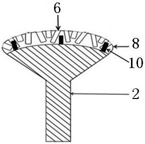
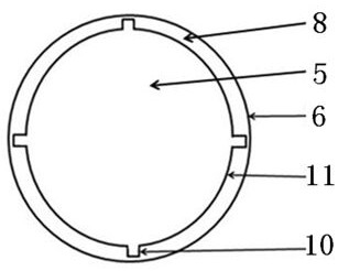
[0094] Such as figure 1 There is no groove on the sealing device 8 shown, and there is no limit block 10 on the impeller 5 .

[0095] The sealing device 8 is fixed on the upper end surface of the blade plate 2 of the impeller 5 and the baffle 11 , and the sealing device 8 is fixed on the side surface of the baffle 11 .

[0096] Described guide pipe 4 is a plastic pipe.

[0097] Such as figure 1 , Figure 5 The high airtight air shutoff device shown in this application is used on vacuum drying processing equipment, and the working effect of the high airtight air shutoff device is:

[0098] The feed port 1 of the highly airtight air locker is fixedly connected to th...


PUM


Abstract

The invention discloses a high-airtightness air seal machine, comprising a valve shell, an impeller, a flow guide pipe and a sealing device. The outer circle sealing surface of the sealing device fixed to the impeller is subjected to turn milling or grinding, and the surface profile tolerance of the outer circle sealing surface of the sealing device meets the precision requirement for high-airtightness use of a small gap between the sealing surface of the sealing device and the inner wall of a valve body. The smooth outer circle sealing surface of the sealing device is fully attached to the inner wall of the valve body, so that the sealing area between the sealing device and the inner wall of the valve body is enlarged. Different pressures of two stock bins corresponding to the left and right sides of the impeller are dredged into balanced and consistent pressures through the flow guide pipe, the pressure intensity and pressure between the two stock bins adjacent to each other up and down on the two sides of the impeller are weakened, and dynamic sealing is conducted between the impeller and the valve body and between the impeller and the side cover through the sealing device, so that the air locking performance of the air seal machine is greatly improved. According to the drying processing equipment, the high-airtightness air seal machine is used in cooperation, and it is guaranteed that the drying processing equipment conducts effective drying work.

Description

technical field [0001] The invention relates to the field of drying processing equipment, in particular to a highly airtight air lock and drying processing equipment. Background technique [0002] The air shutoff device is also called the fan shutoff, unloading valve, ash unloading valve, and star unloader; the main function of the air shutoff device is to continuously input or discharge the materials in the equipment in time, and at the same time reduce the air in the normal pressure environment from entering the load. In the pressure equipment, or to ensure the high pressure in the equipment to reduce leakage in the normal pressure environment. The air lock is used in high-end vacuum drying processing equipment, high-pressure superheated steam drying processing equipment, negative pressure superheated steam drying processing equipment and other equipment. Since the inside of the drying processing equipment is in a state of high pressure or negative pressure, the feed port ...

Claims


Application Information

Patent Timeline
Patent Type & Authority Applications(China)
IPC IPC(8): B65G53/46B65G53/36B65G53/34F26B25/00
CPCB65G53/34B65G53/36B65G53/4625F26B25/002
Inventor 程长青
Owner MENGZHOU YUANHONG DRYING EQUIP RES & DEV CO LTD
Learn More