Three-phase separator

A three-phase separator and shell technology, applied in the field of water treatment, can solve the problems of difficulty in performing their own duties, the sludge cannot reach the optimal sludge age, and the efficiency discount of anaerobic-anoxic-aerobic process, etc. High efficiency, avoid the effect of sludge discharge contradiction

Active Publication Date: 2021-07-30
SUZHOU ZHANQING ENVIRONMENT PROTECTION TECHCO LTD
View PDF13 Cites 2 Cited by
  • Summary
  • Abstract
  • Description
  • Claims
  • Application Information

AI Technical Summary

Problems solved by technology

In the anaerobic-anoxic-aerobic (AAO) process, a large amount of aerobic sludge appears in the anaerobic and anoxic sections due to the unreasonable return of mud and water, and at the same time, the anaerobic sludge flows into the aerobic and anoxic sections. The sludge with various functions is not in its own place, it is difficult to perform its duties, and the efficiency of the entire anaerobic-anoxic-aerobic process is greatly reduced
At the same time, the mixing of sludge in the anaerobic, anoxic, and aerobic stages also led to the inability to differentiate the design of the sludge discharge cycle due to the different biological compositions of each stage. The sludge in the anaerobic, anoxic, and aerobic stages Unable to reach optimal mud age

Method used


Image

  • Three-phase separator
  • Three-phase separator
  • Three-phase separator

Examples


Embodiment

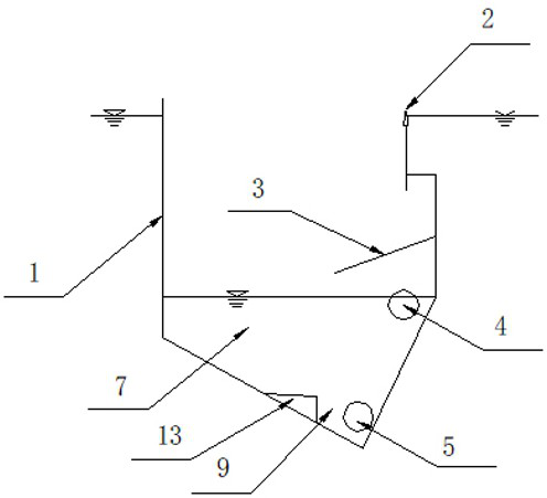
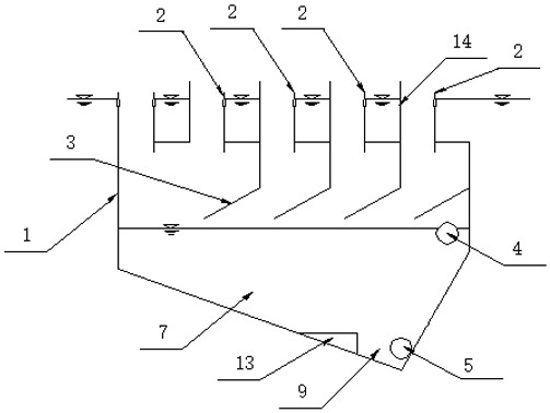
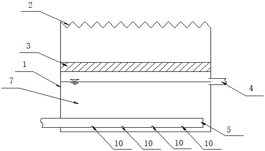
[0020] Embodiment: A three-phase separator, comprising a casing 1, a water drop weir 2, a water drop baffle 3, an outlet pipe 4 and a sludge return pipe 5, the casing 1 is a barrel structure with an open upper end and a closed bottom end, and the outer casing 1. The bottom surface forms a pointed bottom structure with a gradually shrinking cross-section. At least one drop weir 2 is fixedly installed on the inner wall of the opening of the shell 1. At least one drop baffle 3 is fixedly installed on the inner wall of the shell 1. The drop baffle 3 is set in an inclined state, each drop baffle 3 is located directly below the drop weir 2, and the sewage 6 that enters the shell 1 through each drop dam 2 falls to the surface of the drop baffle 3 and then bends back at the set angle and flows into it. At the bottom of the inner side of the housing 1, the outlet pipe 4 and the sludge return pipe 5 are fixedly installed on the housing 1. The water inlet of the outlet pipe is located und...


PUM


Abstract

The invention discloses a three-phase separator comprising a shell, drop weirs, drop baffles, a water outlet pipe and a sludge return pipe; the shell is of a sharp-bottom barrel structure with the upper end open and the lower end closed, at least one drop weir is fixed to the inner side wall of the opening portion of the shell at intervals, and at least one drop baffle arranged in an inclined state is fixed to the inner side wall of the shell; the drop baffles are located under the drop weirs, sewage entering the shell through the drop weirs falls to the surfaces of the drop baffles, then is reversely folded by a set angle and flows into the bottom of the inner side of the shell, and the water outlet pipe and the sludge return pipe are fixed to the shell; a water inlet of the water outlet pipe is located below a position, behind the drop weirs, of the drop baffles; and the water inlet of the water outlet pipe is not higher than the height of water inside the shell, and asludge inlet of the sludge return pipe is located at the bottom tip of the shell. According to the three-phase separator, the problems of three-phase separation and sludge loss in an efficient denitrification process are solved, the problem of mutual interference of sludge in an anaerobic section, an anoxic section and an aerobic section of a biochemical pool is avoided, and the sewage treatment efficiency is improved.

Description

technical field [0001] The invention relates to the technical field of water treatment, in particular to a three-phase separator. Background technique [0002] The high-efficiency denitrification process is mainly based on the denitrification tower and the denitrification filter. The nitrogen generated by the denitrification sludge during the denitrification process is easily combined with the sludge, and the phenomenon of sludge wrapped bubbles often occurs. The denitrification sludge produces After the gas floats up and leaves the reaction zone, it will not only lead to a decrease in the sludge concentration in the reaction zone, which will affect the nitrate nitrogen removal capacity of the process, but will also increase the concentration of floating sludge in the effluent water, which will affect the water quality of the effluent. The three-phase separation technology of the anaerobic process is difficult. Make the denitrification process complete the three-phase separa...

Claims


Application Information

Patent Timeline
Patent Type & Authority Applications(China)
IPC IPC(8): C02F1/20C02F11/127
CPCC02F1/20C02F11/127
Inventor 汤雨林周健丁健赵媛宗兆洋
Owner SUZHOU ZHANQING ENVIRONMENT PROTECTION TECHCO LTD
Why Eureka
Try Eureka