
Pressing mechanism for production of rolling type optical lenses

A technology of optical lenses and pressing mechanism, which is applied in optical components, applications, household appliances, etc. It can solve problems such as inability to discharge air, unstable force application, and large fluctuations, so as to ensure production quality and efficiency, and press-fitting process Smooth, accuracy-enhancing effects

Pending Publication Date: 2021-08-03
吴懋萱
View PDF0 Cites 0 Cited by
  • Summary
  • Abstract
  • Description
  • Claims
  • Application Information

AI Technical Summary

Problems solved by technology

[0003] When traditional equipment manually squeezes multiple optical lenses that are overlapped and bonded together, if the pressure is insufficient, the air cannot be completely discharged. If the force is too strong or too large, it is easy to crush the optical lens. Instability leads to unstable extrusion quality and large fluctuations; and the pressing equipment is not easy to replace, which limits its practical application

Method used


Image

  • Pressing mechanism for production of rolling type optical lenses
  • Pressing mechanism for production of rolling type optical lenses
  • Pressing mechanism for production of rolling type optical lenses

Examples


Embodiment 1

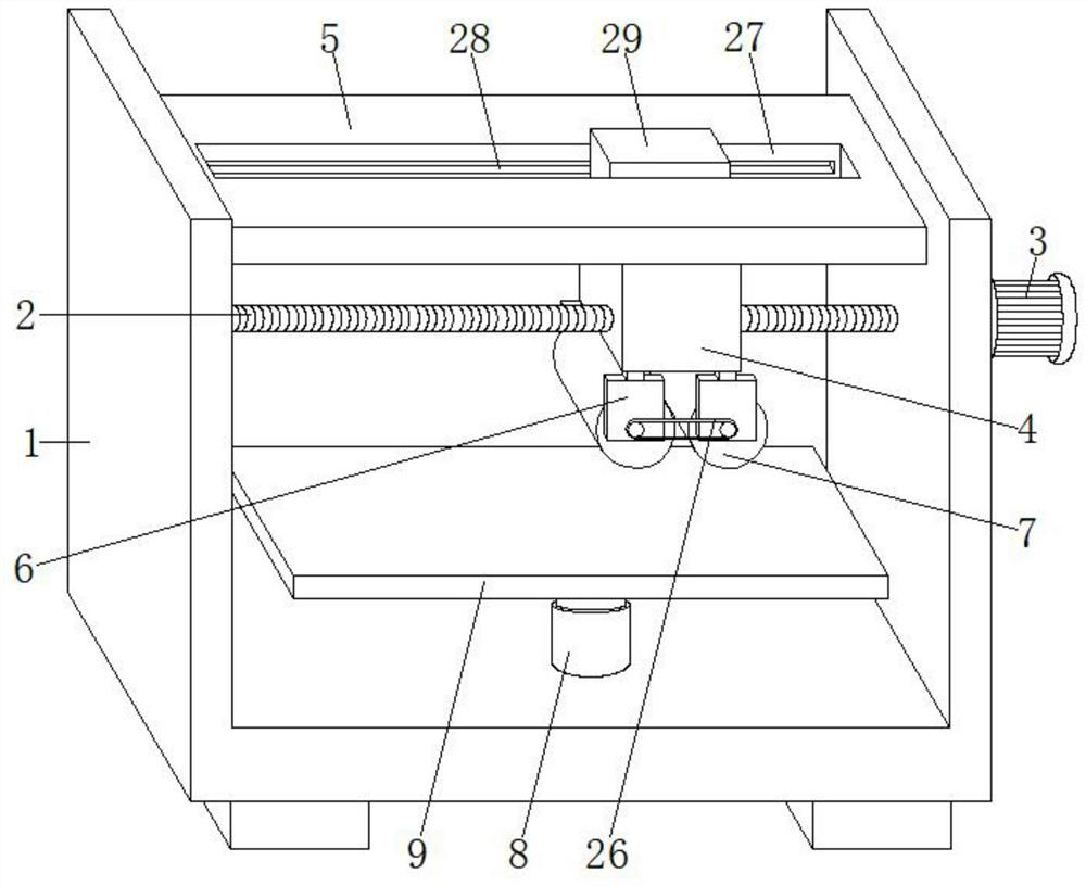
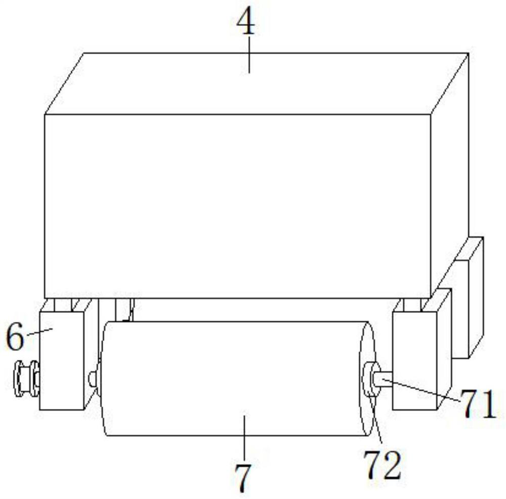
[0033] See Figure 1-5 The present invention provides a technical solution: a pressing mechanism for rolling optical lens production, including press table 1, press table 1 is a U-shaped table, and the inner wall of the pressing table 1 is rotatable to connect a screw 2 The side surface of the pressing table 1 is attached, and the output terminal of the stepping motor 3 is fixedly connected to the screw 2, and the screw 2 is applied to the shift roller 4, and the pressing table 1 is mounted on the press. The plate 5, and the shift roller seat 4 slides on the restricted plate 5, and the bottom of the shift roller 4 has two sets of positioning have two, and a set of positioning has two, and a set of positioning has a position. 6 Returning is mounted, the rolling roller 7 is mounted, and the inner bottom wall of the pressing table 1 is mounted with the automatic telescopic rod 8, and the top end of the automatic telescoping rod 8 is fixedly connected to the tape 9, and the end of the ...

Embodiment 2

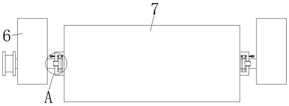
[0043] See figure 1 , 6 -9, and the first embodiment is that the branching mechanism includes a rotating ring 18, a magnetic block A19, a through hole 20, and a magnetic block B21, and the rotating ring 18 is rotated to the positioning tool 6, and the rotating shaft 71 is running through The rotating ring 18 is fixed to the side of the rotating ring 18 close to the side of the pellet 72, and the number of magnetic blocks A19 is two, and the two magnetic block A19 is close to the side of the bits 72. For the anisotropic magnetic pole, the sliding groove 10 is opened to the inner wall of the shaft 71 on the inner wall of the shaft 71, and the displacement plate 11 is fixed to the side of the shaft 71 fixed to the magnetic block B21 corresponding to the through hole 20, and a set of magnetic blocks A19 is respectively Block B21 magnetic phase suction and magnetic repellency.

[0044] The loop-shaped rail groove 22 is opened on the positioning 6, and the rotating ring 18 is fixed to t...


PUM


Abstract

The invention discloses a pressing mechanism for production of rolling type optical lenses. The pressing mechanism comprises a pressing table, wherein the pressing table is a U-shaped table, and a lead screw is rotationally connected to the inner wall of the pressing table; a stepping motor is installed on the side surface of the pressing table, and the output end of the stepping motor is fixedly connected with the lead screw; a shifting roller seat is installed on the lead screw in a threaded mode, a limiting plate is installed on the pressing table, and the shifting roller seat slides on the limiting plate; and two sets of positioning tools are symmetrically installed at the bottom of the shifting roller seat. According to the pressing mechanism for production of the rolling type optical lenses, the shifting roller seat drives a sliding rail to slide in a guide groove, so that movement of the shifting roller seat is more stable, and then the accuracy of subsequent pressing is enhanced; and therefore, when the shifting roller seat moves, a rolling roller of the shifting roller seat can roll, so that sliding friction between the rolling roller and the diameter of an optical lens is changed into rolling friction, on one hand, loss of the optical lens is reduced, on the other hand, the pressing quality is better, and the pressing process is smooth.

Description

Technical field [0001] The present invention relates to the field of optical lens production, and is specifically a pressing mechanism for rolling optical lenses. Background technique [0002] It is well known that the thickness of the single-piece optical lens is very thin, and when the optical lens clamping the alternative optical lens is cut, the optical lens is easily shattered or leaving a clamping on the optical lens, and the optical lens is damaged, so the company will generally The multi-piece optical lens superimposes bonds together to form a thick optical lens, and then the thick optical lens is cut. In the process of overlapping the multi-seiphery optical lens, the enterprise is easily presented between the adjacent optical lenses, which is to form bubbles in the binder adjacent to two optical lenses, which in turn affect the adjacent two pieces. The adhesion between the optical lens, when cutting the thick optical lens, the adjacent two optical lenses suddenly separat...

Claims


Application Information

Patent Timeline
Patent Type & Authority Applications(China)
IPC IPC(8): B29C65/52B29L11/00
CPCB29C65/48B29C66/0322B29L2011/0016
Inventor 吴懋萱
Owner 吴懋萱
Learn More