
Plastic explosive cutting mechanism

A technology of explosives and plasticity, applied in explosives, explosives processing equipment, offensive equipment, etc., can solve the problems of high labor intensity, large weight error of plastic explosive blocks, and low production efficiency, so as to reduce labor intensity, eliminate potential safety hazards, and improve The effect of production safety

Pending Publication Date: 2021-08-03
GUANGDONG MINGHUA MACHINERY
View PDF1 Cites 4 Cited by
  • Summary
  • Abstract
  • Description
  • Claims
  • Application Information

AI Technical Summary

Problems solved by technology

Before smashing the explosives, the plastic explosives need to be cut into plastic explosive blocks with the same weight. However, due to the particularity of plastic explosives, the existing cutting process of plastic explosives is manually carried out by operators, and complete human-machine isolation cannot be achieved. ; and the weight error of the plastic explosive blocks manually cut out is relatively large, it is necessary to add an additional process of weighing the powder after the cutting, to reduce the weight error between the plastic explosive blocks, to ensure that the weight of the explosives smashed into the grenade is consistent
Therefore, in the existing operation of cutting plastic explosives, there are many problems such as many operators, high labor intensity, low production efficiency, and direct contact of operators with explosives.

Method used


Image

  • Plastic explosive cutting mechanism
  • Plastic explosive cutting mechanism
  • Plastic explosive cutting mechanism

Examples


Embodiment Construction

[0034] The technical solutions of the present invention will be further described below in conjunction with the accompanying drawings and through specific implementation methods.

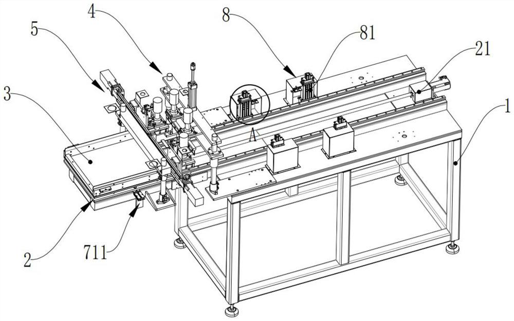
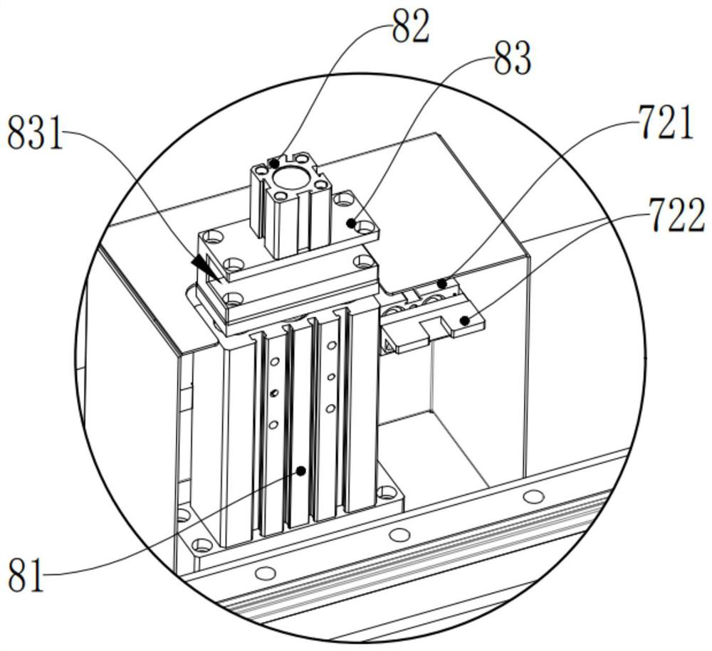
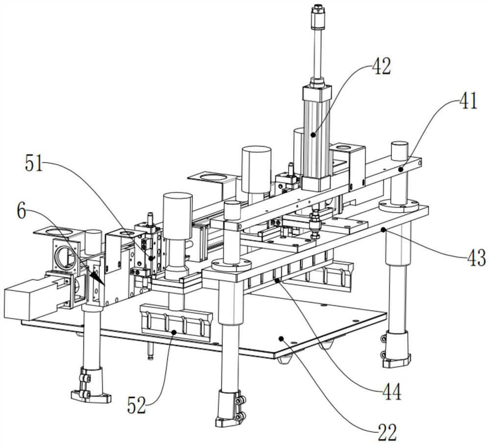
[0035] For a plastic explosive cutting mechanism of this embodiment, refer to the attached figure 1 , including a workbench 1 and a linear movement assembly 2, a drug-carrying tray 3, a first punching assembly 4, a second punching assembly 5, and a translation assembly 6 arranged on the worktable 1;

[0036] The first punching assembly 4 and the translation assembly 6 are arranged on the top of the linear movement assembly 2, the second punching assembly 5 is arranged at the movable end of the translation assembly 6, and the drug-loaded tray 3 is detachably arranged at the movable end of the linear movement assembly 2 , the drug-loaded tray 3 is used to carry plastic explosives, and a silica gel layer is laid on the drug-loaded tray 3;

[0037] The first punching assembly 4 is used for transverse p...


PUM


Abstract

The invention discloses a plastic explosive cutting mechanism, and belongs to the field of grenade production. The plastic explosive cutting mechanism comprises a linear moving component, an explosive carrying tray, a first punching component, a second punching component and a translation component. The first punching assembly and the translation assembly are arranged above the linear moving assembly front and back, the second punching assembly is arranged at the movable end of the translation assembly, the explosive carrying tray is detachably arranged at the movable end of the linear moving assembly, the explosive carrying tray is used for carrying plastic explosives, and a silica gel layer is laid on the explosive carrying tray; the linear driving assembly drives the explosive carrying tray to move front and back under the first punching assembly and the second punching assembly, so that the first punching assembly and the second punching assembly punch plastic explosives in the transverse direction and the longitudinal direction respectively, plastic explosive blocks with the same weight are obtained through cutting, automatic punching of the plastic explosive blocks is achieved, potential safety hazards caused by direct contact between operators and explosives are eliminated, the production safety is improved, and the labor intensity is reduced.

Description

technical field [0001] The invention relates to the field of grenade production, in particular to a plastic explosive cutting mechanism. Background technique [0002] Plastic explosives have plasticity, good consistency and viscosity, are prone to irreversible deformation under the action of external force, are easy to stick to each other into groups or knead into desired shapes, and have higher density and greater explosive power. It is easy to fill complex projectile shapes and irregular blastholes, so plastic explosives are widely used in military products such as grenades. However, due to the high viscosity of the plastic explosive, it is easy to stick to the mechanism that is in direct contact with the powder. [0003] Chinese invention application CN201920952292.7 discloses a production line for grenade multi-shot automatic charging and pressing, which uses the method of automatic pounding and scraping. The explosives are loaded into the shell of the grenade through t...

Claims


Application Information

Patent Timeline
Patent Type & Authority Applications(China)
IPC IPC(8): C06B21/00
CPCC06B21/00Y02W30/62
Inventor 孔祥盛张鑫贾琛黄明星
Owner GUANGDONG MINGHUA MACHINERY
Learn More