Cooling structure design method of high-pressure turbine guide cooling blade margin plate

A cooling structure and high-pressure turbine technology, applied in mechanical equipment, stators, engine components, etc., can solve problems such as ablation, low cooling effect, and single cooling structure, and achieve the goal of reducing hot spot temperature, improving cooling effect, and improving blade life Effect

Active Publication Date: 2021-08-03
AECC SHENYANG ENGINE RES INST
View PDF8 Cites 3 Cited by
  • Summary
  • Abstract
  • Description
  • Claims
  • Application Information

AI Technical Summary

Problems solved by technology

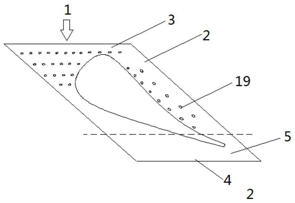
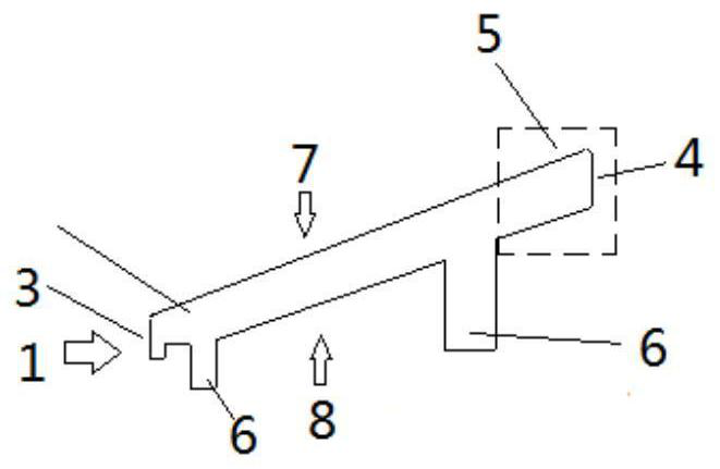
The existing high-pressure turbine guide vane edge plate air film cooling has the following disadvantages: the cooling structure is single, affected by the channel vortex on the side of the blade pot, the covering effect is poor, and the cooling effect is low; Affected by these factors, the cooling effect is unstable; limited by the interference of the vertical plate on the edge plate and the processing angle of the air film hole, it is not easy to open holes in some positions such as the axial tail area (such as figure 2 As shown, it is not easy to open the film hole area 5). If the hole is opened, the angle between the hole and the wall surface will be too small, which will lead to a low processing pass rate. Faults such as ablation and block loss

Method used


Image

  • Cooling structure design method of high-pressure turbine guide cooling blade margin plate
  • Cooling structure design method of high-pressure turbine guide cooling blade margin plate
  • Cooling structure design method of high-pressure turbine guide cooling blade margin plate

Examples


Embodiment Construction

[0046] In order to make the purpose, technical solution and advantages of the application more clear, the technical solution in the embodiment of the application will be described in more detail below in conjunction with the drawings in the embodiment of the application. In the drawings, the same or similar reference numerals denote the same or similar elements or elements having the same or similar functions throughout. The described embodiments are some, but not all, embodiments of the application. The embodiments described below by referring to the figures are exemplary, and are intended to explain the present application, and should not be construed as limiting the present application. Based on the embodiments in this application, all other embodiments obtained by persons of ordinary skill in the art without creative efforts fall within the protection scope of this application. Embodiments of the present application will be described in detail below in conjunction with th...


PUM


Abstract

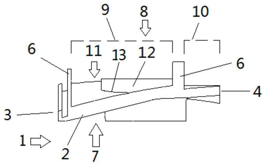
The invention belongs to the field of aero-engine blades, and particularly relates to a cooling structure design method for a high-pressure turbine guide cooling blade margin plate. The cooling structure design method for the high-pressure turbine guide cooling blade margin plate comprises the steps that firstly, the margin plate is partitioned into a cold air introduction area and a non-cold air introduction area according to the air introduction position of the margin plate and the position of a vertical plate; secondly, an impact and air film combined cooling structure is designed in the cold air introduction area of the margin plate; thirdly, a turbulent flow column and air film combined cooling structure is designed in the non-cold air introduction area of the margin plate; fourthly, gas film cooling structures are designed on the fuel gas side surface of the margin plate and a blade body close to the margin plate; and fifthly, variable-radius fillets are arranged on the connecting sections of the margin plate and the blade body along a blade profile. According to the cooling structure design method for the high-pressure turbine guide cooling blade margin plate, a combined cooling mode is adopted for cooling the wall face of the high-pressure turbine guide blade margin plate, the hot-spot temperature of the margin plate can be reduced, the cooling effect of the blade margin plate can be improved, and the service life of blades can be prolonged.

Description

technical field [0001] The application belongs to the field of aeroengine blades, in particular to a method for designing a cooling structure of a high-pressure turbine guide cooling blade edge plate. Background technique [0002] As the temperature in front of the turbine increases, the cooling problem of the turbine blade edge plate becomes more and more prominent. Due to the existence of fluid viscosity and the influence of radial, circumferential and axial pressure gradients, the existence of the cascade end wall effect, the blade edge plate area is the most complex area of ​​the aerodynamic structure in the blade channel, and the secondary flow phenomenon is very complicated , the existence of horseshoe vortex, channel vortex, corner vortex, and the adsorption and separation of flow directly affect the heat load distribution of the blade, resulting in multiple hot spots, such as: leading edge area, suction surface convex area, pressure surface and pressure surface The ...

Claims


Application Information

Patent Timeline
Patent Type & Authority Applications(China)
IPC IPC(8): F01D9/04F01D9/06
CPCF01D9/041F01D9/065Y02T50/60
Inventor 屈云凤陶一鸾左可军吕博文张志强
Owner AECC SHENYANG ENGINE RES INST
Why Eureka
Try Eureka