Planar transmission line structure for improving ferromagnetic resonance linewidth test precision

A technology of planar transmission lines and ferromagnetic resonance lines, applied in measuring devices, using electromagnetic means, instruments, etc., can solve the problems of increasing signal line width, large dielectric loss, and poor signal isolation, so as to eliminate return loss, The dielectric constant is moderate and the effect of improving the test accuracy

Pending Publication Date: 2021-08-03
UNIV OF ELECTRONICS SCI & TECH OF CHINA
View PDF6 Cites 1 Cited by
  • Summary
  • Abstract
  • Description
  • Claims
  • Application Information

AI Technical Summary

Problems solved by technology

Enlarging the signal line width of the grounded coplanar waveguide will, on the one hand, generate unnecessary stray signals, and on the other hand increase the interaction area between the microwave magnetic field and the sample, which will lead to poor growth uniformity, more defects, and higher anisotropy. Strong film, it is easy to produce irregular ferromagnetic resonance line width external broadening, the real line width cannot be accurately measured
However, when the signal line width is reduced to the process limit value, due to the limitation of the 50 ohm characteristic impedance, the groove spacing often exceeds the process limit value, so it is impossible to realize the grounded coplanar waveguide whose line width is the process limit value
Another photolithographic grounded coplanar waveguide structure not only has poor grounding effect, poor signal isolation, and large dielectric loss, but also has more restrictions on the test sample

Method used


Image

  • Planar transmission line structure for improving ferromagnetic resonance linewidth test precision
  • Planar transmission line structure for improving ferromagnetic resonance linewidth test precision
  • Planar transmission line structure for improving ferromagnetic resonance linewidth test precision

Examples


Embodiment 1

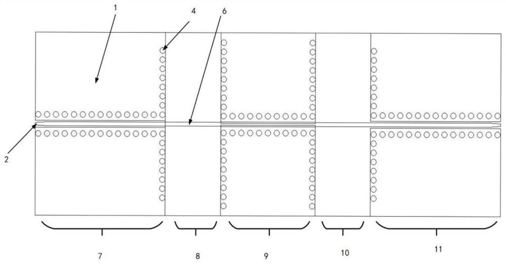
[0029] This embodiment proposes a planar transmission line structure that improves the test accuracy of ferromagnetic resonance line width, such as figure 1 , 2, including the first-level standard characteristic impedance grounded coplanar waveguide 7, the first-level non-standard microstrip line 8, the intermediate level non-standard characteristic impedance grounded coplanar waveguide 9, and the second-level non-standard microstrip line in series. The line 10 and the second-level standard characteristic impedance grounded coplanar waveguide 11; the overall length of the planar transmission line structure is 31.5mm, and the width is 12mm.

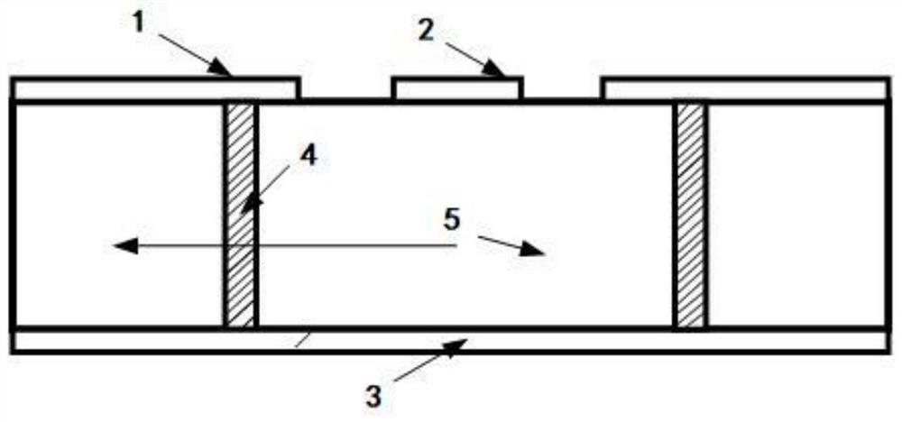
[0030] The first-level standard characteristic impedance grounded coplanar waveguide 7, the first-level non-standard microstrip line 8, the intermediate level non-standard characteristic impedance grounded coplanar waveguide 9, the second-level non-standard microstrip line 10 and the second-level standard The dielectric substrate 5 of the ...

Embodiment 2

[0042] This embodiment proposes a planar transmission line structure that improves the accuracy of ferromagnetic resonance linewidth testing, including the first-level standard characteristic impedance grounded coplanar waveguide 7, the first-level non-standard microstrip line 8, and the intermediate-level non-standard The characteristic impedance grounded coplanar waveguide 9, the second non-standard microstrip line 10 and the second standard characteristic impedance grounded coplanar waveguide 11; the overall length of the planar transmission line structure is 31.5mm, and the width is 12mm.

[0043] The first-level standard characteristic impedance grounded coplanar waveguide 7, the first-level non-standard microstrip line 8, the intermediate level non-standard characteristic impedance grounded coplanar waveguide 9, the second-level non-standard microstrip line 10 and the second-level standard The dielectric substrate 5 of the characteristic impedance grounded coplanar wavegu...


PUM

PropertyMeasurementUnit
lengthaaaaaaaaaa
widthaaaaaaaaaa
thicknessaaaaaaaaaa

Abstract

The invention provides a planar transmission line structure for improving ferromagnetic resonance linewidth test precision, and belongs to the field of microwave millimeter wave band magnetic material parameter test. The planar transmission line structure comprises a first-stage standard characteristic impedance grounding coplanar waveguide, a first-stage non-standard microstrip line, an intermediate-stage non-standard characteristic impedance grounding coplanar waveguide, a second-stage non-standard microstrip line and a second-stage standard characteristic impedance grounding coplanar waveguide which are sequentially connected in series; the characteristic impedance of the first-stage standard characteristic impedance grounding coplanar waveguide, the characteristic impedance of the second-stage standard characteristic impedance grounding coplanar waveguide, and the characteristic impedance of a transmission line composed of the first-stage non-standard microstrip line, the middle-stage non-standard characteristic impedance grounding coplanar waveguide and the second-stage non-standard microstrip line are 50 ohms. The signal line width and the slot spacing of the middle-stage non-standard characteristic impedance grounding coplanar waveguide are process limit values; and the lengths of the first-stage and second-stage non-standard microstrip lines are 1 / 4 of the central frequency wavelength. Through multi-stage transmission line conversion, the grounding coplanar waveguide with the signal line width and the groove spacing being the process limit values is realized, and the test precision is improved.

Description

technical field [0001] The invention belongs to the field of microwave and millimeter wave band magnetic material parameter testing, and in particular relates to a planar transmission line structure for improving the testing accuracy of ferromagnetic resonance line width. Background technique [0002] Under the background of the rapid development of wireless microwave communication, the operating frequency of each part of the core components of the communication system gradually enters the microwave band and the millimeter wave band. requirements, traditional devices are no longer applicable. With the discovery of the giant magnetoresistance effect, magnetic material devices have gradually highlighted their huge application potential due to their small size, high precision, and fast speed, because of their small footprint, high usable frequency, strong anisotropy, and low loss. It has been widely used in microwave communication devices such as circulators and isolators, gre...

Claims


Application Information

Patent Timeline
Patent Type & Authority Applications(China)
IPC IPC(8): G01B7/02H01P3/00H01P3/08
CPCG01B7/02H01P3/081H01P3/006
Inventor 张怀武吴永锐金立川钟智勇白飞明
Owner UNIV OF ELECTRONICS SCI & TECH OF CHINA
Why Eureka
Try Eureka