Gas-liquid-sand mixed fluid automatic desanding system for natural gas extraction

A technology of mixing fluid and natural gas, applied in the field of machinery, can solve the problems of unsuitable cyclone separation, high working intensity, and high frequency of sand discharge, and achieve the effect of reducing sand-liquid separation work, improving equipment adaptability, and large flow adaptability range.

Inactive Publication Date: 2021-08-06
成都汇川新能科技有限公司 +1
View PDF11 Cites 3 Cited by
  • Summary
  • Abstract
  • Description
  • Claims
  • Application Information

AI Technical Summary

Problems solved by technology

[0003] Due to the large flow rate of high-pressure gas in filtration and separation, when the filter element is gradually blocked by sand particles, the differential pressure of the desander is very high. It is necessary to frequently open the desander, take out the filter element for cleaning, and work intensively.
The scope of cyclone separation is limited. The production difference between the initial stage and the end stage of a shale gas well is huge, and cyclone separation cannot adapt
[0004] The existing desander needs to be closed regularly to discharge the sand, or to configure the sand accumulation tank to discharge the sand regularly. Wells with a large amount of sand need to be operated many times a day, resulting in a large manual workload
The current sand discharger is basically unable to check the amount of sand accumulated. When the sand is not discharged in time manually, the sand accumulates and flows directly downstream, causing equipment damage
[0005] In the current desander, the liquid and the sand are basically not separated. When discharging the sand, the liquid and the sand are discharged together, resulting in a high frequency of sand discharge and a large amount of liquid discharge, which requires a large space for storage and processing.

Method used


Image

  • Gas-liquid-sand mixed fluid automatic desanding system for natural gas extraction

Examples


Embodiment Construction

[0023] The specific embodiment of the present invention will be further described in detail below in conjunction with the accompanying drawings.

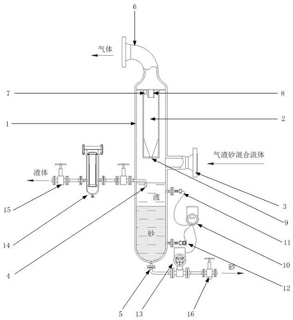
[0024] The gas-liquid-sand mixed fluid automatic desanding system for natural gas exploitation according to the present invention comprises a shell 1 and a desanding feed port 3 on the shell, and inside the shell is a main separation chamber communicated with the desanding feed port 3 , a first liquid discharge port 4 and a sand discharge port 5 are arranged below the sand removal inlet; an automatic sand discharge branch is connected to the sand discharge port;

[0025] The sand discharge system also includes an automatic control system, the automatic control system includes a controller 10 and a sand level detector 11 and a liquid level detector 12 connected thereto, the sand level detector 11 is installed below the main separation chamber, The liquid level detector 12 is installed between the installation height of the sand level...


PUM


Abstract

A gas-liquid-sand mixed fluid automatic desanding system for natural gas extraction comprises a shell and a desanding feeding port in the shell, a main separation cavity communicating with the desanding feeding port is formed in the shell, a first liquid discharging port and a sand discharging port are formed below the desanding feeding port, and the sand discharge port is connected with an automatic sand discharge branch; and a sand discharging system further comprises an automatic control system, the automatic control system comprises a controller, a sand level detector and a liquid level detector, the sand level detector and the liquid level detector are connected with the controller, the sand level detector is installed below the main separation cavity, the liquid level detector is installed between the installation height of the sand level detector and the installation height of the sand discharging opening, and the automatic sand discharging branch is controlled by the controller. By arranging a sensor and the control system, sand can be automatically discharged according to the stacking height in a sand remover, the whole sand discharging process is fully automatically completed, and manual operation is greatly reduced; and liquid is discharged through the liquid outlet, so that the desilting operation frequency and the subsequent sand-liquid separation work are reduced. By arranging a cyclone sand discharger, the equipment adaptability is improved, the advantages of gravity settling and cyclone separation are integrated, and the flow adaptation range is large.

Description

technical field [0001] The invention belongs to the technical field of machinery, and relates to desanding equipment, in particular to an automatic desanding system for gas-liquid-sand mixed fluid used in natural gas exploitation. Background technique [0002] Natural gas extraction, especially unconventional natural gas such as shale gas and tight gas, contains a large amount of liquid and sand in the gas. The high-speed sand particles in the high-pressure gas flow will cause serious damage to the natural gas gathering and transportation equipment. The desander is the key equipment to remove the sand in the fluid. By using the desander, the sand mixed with the high-pressure fluid in the pipeline is separated and discharged out of the pipeline system. Most of the currently used desanders are filtered through filters or cyclone separation to separate the sand particles and then discharged regularly. [0003] Due to the large flow rate of high-pressure gas in filtration and ...

Claims


Application Information

Patent Timeline
Patent Type & Authority Applications(China)
IPC IPC(8): B01D50/00E21B43/34
CPCE21B43/34B01D50/20
Inventor 黄林川
Owner 成都汇川新能科技有限公司
Why Eureka
Try Eureka